- Joined
- Nov 17, 2018
- Messages
- 68
- Reaction score
- 64
- Age
- 50
Does anyone have any information about the Solo Controller's I.MX6 schematics?
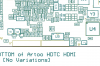
Attached are photos of the board - in particular I see
J9: - Labelled as Power
Vin 7 to 24 V dc
Gnd
5v
J3 - The connector that goes to the STM32 board, which has 10 pins. We can probably make a guess that this has
- Ov and 5v
- At least one Serial RX. TX to the STM32
- Maybe another serial to the IMX RX,TX, CTS, RTS on the STM32 board
Those are not the mystery...I'm really more interested in
J10 - 6 pins
J1 - 5 pins
J5 - 5 pins
In 2015, The FCC filings for the controller where submitted. As per the link below, the schematics were part of that bundle - but kept confidential. Given the Solo is no longer in production, and the code that runs on this is open source, I'm hoping someone (maybe someone who has a contact who was at 3DR back in 2015), might be ok say what those connector pinouts are. The FCC page is at FCC ID 2ADYD-AT11A Handheld Remote Control Transmitter by 3D Robotics, Inc
I'm thinking the 6 pin connector could maybe consist or such as:
Serial - Ov, V+, TX, RX, CTS, RTS
I wonder if the one of the 5/6 pin connector could be USB OTG. .. We know the the main chip on the board is a IMX6 (arm SoC) running linux and has both as USB OTG and USB host capability. The info for that is at MCIMX6Q6AVT10AC Product Information|NXP data sheet = https://www.nxp.com/docs/en/data-sheet/IMX6DQAEC.pdf
However those pins could be other things - e.g. GPIO, Canbus, UARTS.... .. Only someone who's seen the schematic would probably know this (unless someone could x-ray the circuit board and trace back the pins to the SoC's ball pads!)
Can anyone help with info around the artoo IMX6's pinouts please?
Thx!!