I am in the process of designing a simple 1-axis (tilt) gimbal for a Sony mirrorless camera for use on my Solos. Will use a yet-to-be-selected servo to tilt the camera on the gimbal. Am curious about wiring options for such a tilt servo. Must I tap into the mainboard or can I use the existing Solo GoPro gimbal cable? The paddle control on the radio already can tilt the GoPro gimbal, so I assume the gimbal cable is delivering power (easy), and a control signal of some kind (not so easy), both from the mainboard to the GP gimbal. Apologies in advance for some pretty basic/stupid questions (perhaps someone else can learn something).
I have been using Sony alpha series cameras on Solos for a while. Currently use fixed mounts from carbon fiber for these cameras. A rigid mount is crucial otherwise the added weight (333g) from the camera will cause the Solo to be unstable in flight. I use a remote control device to trigger the shutter and control Av, shutter speed, ISO, focus, zoom etc… See Mount and Camera Remote Control Options for Non-GoPro Cameras Others are way ahead of me on this topic, see
 3drpilots.com
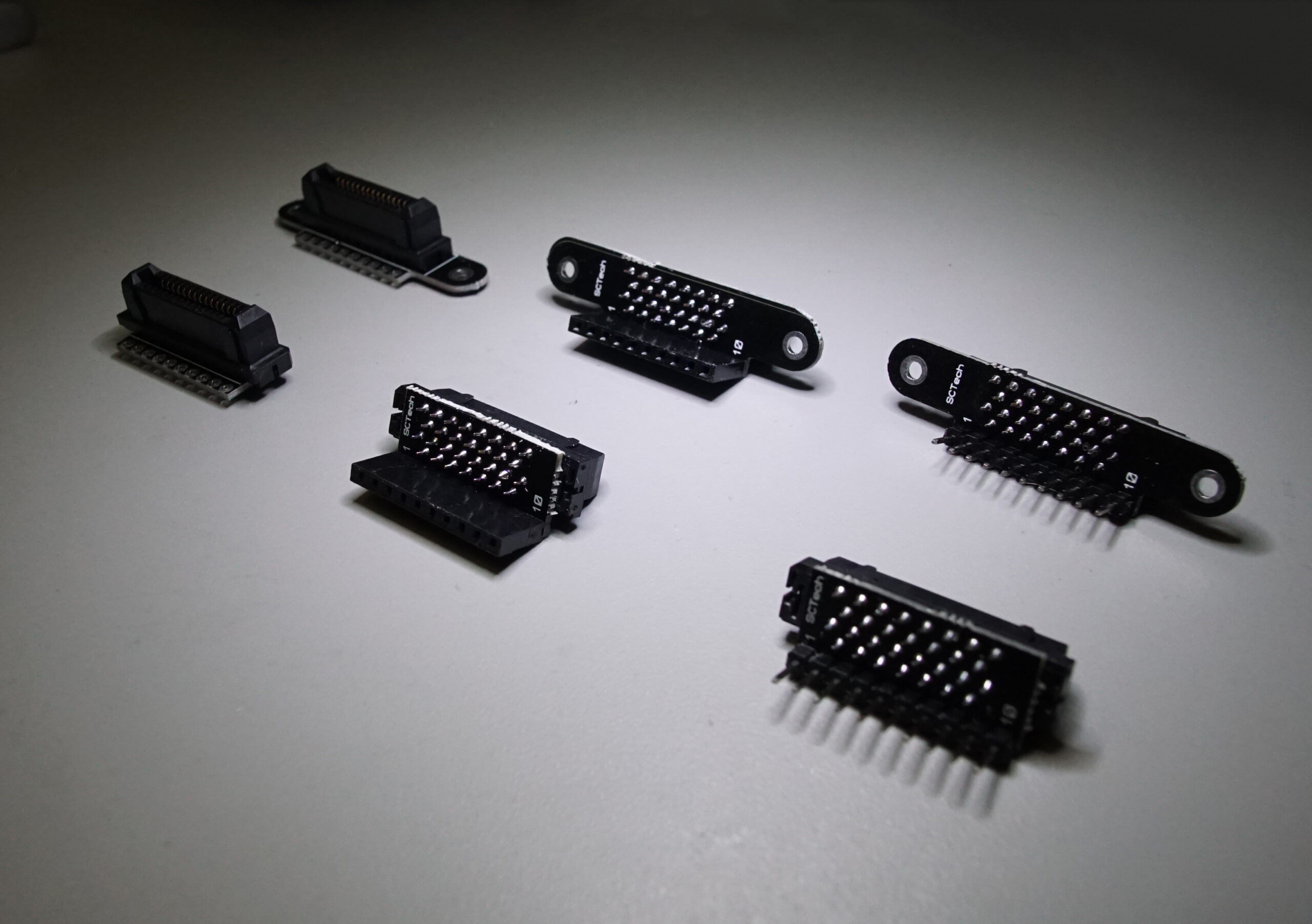
I already have Solo gimbal breakout cables and small breakout boards. I have been using these to power the small camera remote control device mounted to my Solos. The onboard gimbal cable plugs into the Molex connector on these.

My questions are:
If I am left only with pin/wire 2, can I use that pin/wire to power BOTH the new Servo and the Camera Remote Control Device that is already on that power line. The latter draws very little power and would never be used at the same time as the new tilt servo. Tilt camera first, trigger shutter second.
Assuming, power can be pulled on one of the pins/wires, which ground should be used? Pin/wire 3 or 4?
Solo Gimbal Cable (from the DevGuide)
The Solo Gimbal cable terminates in a Molex 5031490800 (alt link) connector. A gimbal board is connected using the corresponding Molex 5031540890 (alt link) connector.
Q2/PWM Signal Options: the common method to connect a new servo is to solder the signal cable from the servo to the Solo mainboard on Pin14 IO-CH6/PWM6 and then turn that Ch 6 ON in Mission Planner. I understand that doing this enables the paddle controller on the Solo radio to trigger the NEW Servo in parallel to the existing GoPro gimbal tilt movement that must be already be enabled via the Solo Gimbal Cable communicating a tilt signal of some kind from the mainboard/radio/paddle.
If this is the case, can I just tap into the Gimbal cable instead of soldering to Pin 14 on the mainboard? It would be simpler for me to use one of my existing breakout connectors rather than solder the signal cable on to the mainboard. I just want to make sure before I go down the path of opening and mangling my mainboard with my pathetic and dangerous soldering skills.
It appears that wires/Pins 5 and 6 (maybe 7 and 8 as well) on the Solo Gimbal Cable (labeled Gimbal Rx White and Gimbal Tx Green in the Solo Development Guide) would be for camera triggering and tilt (see next paragraph). Assuming the mainboard signal is compatible with the new Servo, if one has a gimbal breakout cable (as I do), it would not be necessary to connect the new servo to the mainboard. Instead, I would connect it to the existing wire 5 or 6 on the breakout cable (I assume it would be 6). I understand that this would only work if the mainboard is sending a PWM signal over this pin/wire. As indicated below, I suspect it does not (and the GoPro gimbal is controlled another way).
From the Development Guide: “The Gimbal TX and Gimbal RX lines send MAVLink data over a serial connection between the Pixhawk flight controller and the GoPro gimbal.” I take this to mean that the tilt signal to the GoPro gimbal is not a simple PWM signal of the type that will be needed for a new Tilt Servo on a new camera mount. Sorry for burying the punchline, but does this kill the idea of controlling a new Servo via the existing GoPro gimbal cable?
If it does, the next question becomes whether there is a motor device other than a pwm Servo that can be considered to power and control tilt? Given the lighter weights involved with the GoPro gimbal, I suspect not…
I have been using Sony alpha series cameras on Solos for a while. Currently use fixed mounts from carbon fiber for these cameras. A rigid mount is crucial otherwise the added weight (333g) from the camera will cause the Solo to be unstable in flight. I use a remote control device to trigger the shutter and control Av, shutter speed, ISO, focus, zoom etc… See Mount and Camera Remote Control Options for Non-GoPro Cameras Others are way ahead of me on this topic, see
Nikon J5 mirrorless camera on 3Dr Solo - ch7 shutter
For anyone interested I have finally made up a mount and mounted a small servo on top of my Nikon J5 to activate the shutter using the pause button on the controller. This bird has open solo and I finally soldered another servo wire in and set up ch7, long press to activate shutter and short...
3drpilots.com
I already have Solo gimbal breakout cables and small breakout boards. I have been using these to power the small camera remote control device mounted to my Solos. The onboard gimbal cable plugs into the Molex connector on these.
My questions are:
- Can I power the new servo via the gimbal break out cable or board in addition to the camera remote control device that is already connected to the gimbal cable on pins/wires 2 (5V) and 4 (USB GND)?
- Will one of the other pins/wires on the gimbal cable be usable to deliver the necessary PWM signal to the new servo so I can use the paddle on the radio to control the tilt on the new gimbal via the servo?
If I am left only with pin/wire 2, can I use that pin/wire to power BOTH the new Servo and the Camera Remote Control Device that is already on that power line. The latter draws very little power and would never be used at the same time as the new tilt servo. Tilt camera first, trigger shutter second.
Assuming, power can be pulled on one of the pins/wires, which ground should be used? Pin/wire 3 or 4?
Solo Gimbal Cable (from the DevGuide)
The Solo Gimbal cable terminates in a Molex 5031490800 (alt link) connector. A gimbal board is connected using the corresponding Molex 5031540890 (alt link) connector.
Pin | Name | Color | Description |
| 1 | VCC Battery | Red | 12V to 16.8V. Max recommended current/power is ~3A/50W. Drawing additional current may damage the battery and increases the risk of accident. |
| 2 | VCC 5V | Yellow | 4.75V to 5.4V voltage pin for Camera (only). Current should be less than 1A. |
| 3 | GND (Gimbal) | Black | |
| 4 | GND (USB) | Brown | |
| 5 | Gimbal Rx | White | |
| 6 | Gimbal Tx | Green | |
| 7 | USB D+ | Blue | Positive differential data signal to iMX6 OTG USB port. |
| 8 | USB D- | Violet | Negative differential data signal to iMX6 OTG USB port. |
Q2/PWM Signal Options: the common method to connect a new servo is to solder the signal cable from the servo to the Solo mainboard on Pin14 IO-CH6/PWM6 and then turn that Ch 6 ON in Mission Planner. I understand that doing this enables the paddle controller on the Solo radio to trigger the NEW Servo in parallel to the existing GoPro gimbal tilt movement that must be already be enabled via the Solo Gimbal Cable communicating a tilt signal of some kind from the mainboard/radio/paddle.
If this is the case, can I just tap into the Gimbal cable instead of soldering to Pin 14 on the mainboard? It would be simpler for me to use one of my existing breakout connectors rather than solder the signal cable on to the mainboard. I just want to make sure before I go down the path of opening and mangling my mainboard with my pathetic and dangerous soldering skills.
It appears that wires/Pins 5 and 6 (maybe 7 and 8 as well) on the Solo Gimbal Cable (labeled Gimbal Rx White and Gimbal Tx Green in the Solo Development Guide) would be for camera triggering and tilt (see next paragraph). Assuming the mainboard signal is compatible with the new Servo, if one has a gimbal breakout cable (as I do), it would not be necessary to connect the new servo to the mainboard. Instead, I would connect it to the existing wire 5 or 6 on the breakout cable (I assume it would be 6). I understand that this would only work if the mainboard is sending a PWM signal over this pin/wire. As indicated below, I suspect it does not (and the GoPro gimbal is controlled another way).
From the Development Guide: “The Gimbal TX and Gimbal RX lines send MAVLink data over a serial connection between the Pixhawk flight controller and the GoPro gimbal.” I take this to mean that the tilt signal to the GoPro gimbal is not a simple PWM signal of the type that will be needed for a new Tilt Servo on a new camera mount. Sorry for burying the punchline, but does this kill the idea of controlling a new Servo via the existing GoPro gimbal cable?
If it does, the next question becomes whether there is a motor device other than a pwm Servo that can be considered to power and control tilt? Given the lighter weights involved with the GoPro gimbal, I suspect not…