Pixhawk 2.1 Cube on Solo

Joined
Nov 3, 2016
Messages
82
Reaction score
26
Age
43
So I'm aware that the normal Pixhawk 2.1 doesn't work on Solo without soldering a jumper on the board.

Where is this jumper?

I wasn't able to find a Green Cube in stock anywhere, so I ordered a 2.1 and am comfortable soldering- though I can't find any documentation on where on the board the jumper is.

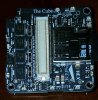
The 2.1 looks like this inside- are the pads on the bottom center what needs to be soldered?
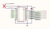
http://docs.uavos.com/images/xhawk-fmuv3-top-mod.jpg
 
The jumper should be locatable via the attached rendering from the 3DR PixHawk documentation.
The last revision of the Pixhawk2.0 that apparently never made it into production had the jumper and improved drive that the Pixhawk2.1/GreenCube has.
You will need to cut the existing trace and put a solder blob to the other VCC selection.
 

Attachments

  • Jumper.png
    Jumper.png
    733.6 KB · Views: 408
  • Like
Reactions: TimCar
The jumper should be locatable via the attached rendering from the 3DR PixHawk documentation.
The last revision of the Pixhawk2.0 that apparently never made it into production had the jumper and improved drive that the Pixhawk2.1/GreenCube has.
You will need to cut the existing trace and put a solder blob to the other VCC selection.
Thanks, that's exactly what I was looking for!
 
So I can confirm that this works, Solo flys great.

It's a small space to be working/soldering, if anyone is going to attempt it, have a steady hand!
 

Attachments

  • cube.jpg
    cube.jpg
    379.1 KB · Views: 373
  • Like
Reactions: Derriell and XevetS
Is this really all they did for the "Green Cube", switch over the trace to connect to 5V and put it in a green case?
 
Is this really all they did for the "Green Cube", switch over the trace to connect to 5V and put it in a green case?
Not quite. Vibration isolation, heated IMUs, updated chipset/sensors, and yes, 5v signaling by default (compared to the Pixhawk 2.0 Cube). Between the 2.1 Black/Green, the difference is just the 3v/5v signaling by default, but both share the updated harwdare versus the V2.0.
 
  • Like
Reactions: XevetS
I know it has been awhile since this thread was started, but thank you to cynfab and yarr for posting the pictures — I have not been able to find this information elsewhere, so this was very helpful.

However, the procedure is not clear to me, and I want to be absolutely sure before I make the modification. I can make an assumption, but would rather verify. If we number the pads 1, 2, and 3, where “1” is the pad closest to the plastic socket — I understand the trace between 2 and 3 must be cut, correct? Is it then pads 1 and 2 that are bridged?
 
If you look at the pads before you do anything to the PH2.1, you will see a trace between the middle one and the one to the outside of the PH2.1. This is the trace that must be cut and the new solder bridge needs to be applied between the middle and the inner pad.
The middle pad is the VCCB of the level shifter and the outer pad is the default setting (3.3V) for the PH2.1. Cut that trace and bridge to the other pad which is 5.0V.
Your goal is to switch the VCCB of the level shifter from the default of 3.3V to the alternate of 5.0V.
proficnc or jesters should have this procedure for you to follow, but if you need any other assistance ---->> just ask.
 
  • Like
Reactions: Kiraniv Group
I'm going to spend the money to do this, but can someone please give me a better illustration. There's a pic above with some arrows on it above but I really don't understand what to do. So far THIS is the place that has come the closest with providing me with accurate info. I would just buy a pixhawk green cube, but theyre literally sold out
 
To switch a PH2.1 to PH2.1 Green you need to be comfortable soldering and working in very close quarters.
Procedure:
1. obtain PH2.1
2. open bottom where main connector is, this may require some skill with an X-acto knife.
3. locate jumper pads, that is what the pictogram above is for.
4. cut the small trace.
5. make a solder blob between the centre and the other pad.
6. check for shorts.
7. clean up flux residue.
8. put cube back together.
9. enjoy the "Green" goodness
10. don't fall out of the sky.

I don't have a PH2.1 so I can't take any detailed pix of the effected area, but I have modified 3 PH2.0 cubes as detailed elsewhere. I use a stereo zoom microscope, it helps a lot.
 
  • Like
Reactions: yarrr
I don't have a PH2.1 so I can't take any detailed pix of the effected area, but I have modified 3 PH2.0 cubes as detailed elsewhere. I use a stereo zoom microscope, it helps a lot.

I'm going to do 5V mod in my PH2.0, did you follow madhacker procedure to install OpenSolo for GreenCube in your modyfied PH2.0 or you just stay with OpenSolo for stock cube?
 
In general... remove the chip, clean up, cut the trace, put the chip back on, clean up, add the jumper. So far all 3 work fine. ;>)) I installed OpenSolo & 3.5.x via a modified version of SoloCli. That procedure is not for everyone, and takes a bit of fiddling but it does work.

Solex & Matt's instructions are the best, hands down.
 
  • Like
Reactions: Anndybo
In general... remove the chip, clean up, cut the trace, put the chip back on, clean up, add the jumper. So far all 3 work fine. ;>)) I installed OpenSolo & 3.5.x via a modified version of SoloCli. That procedure is not for everyone, and takes a bit of fiddling but it does work.

Solex & Matt's instructions are the best, hands down.

Thanks cynfab for your replay, going do the mod this weekend, we see how will go. Then will play with open solo.
 
In general... remove the chip, clean up, cut the trace, put the chip back on, clean up, add the jumper. So far all 3 work fine. ;>)) I installed OpenSolo & 3.5.x via a modified version of SoloCli. That procedure is not for everyone, and takes a bit of fiddling but it does work.

Solex & Matt's instructions are the best, hands down.

Maybe looks to easy but to install Arducopter 3.5.4 in my Cube 2.0 5V after installed Open Solo, I just extracted px4 file from Arducopter 3.5.4.zip for GC and installed it using Mission Planner custom firmware update (usb from PC to Cube usb port). So far looks good.
 
I am also trying to convert my regular Pixhawk Cube 2.1 for 3DR Solo use via jumper. I actually need some more clarity before doing this.

I've found a diagram with JP1 for SN74LVC8T245 (U8002). Is this the "jumper" which the need to connect "VCCB" to "5V5" ?
If so, I would then assume "5V5" is the furthest pin from the plastic connector based on diagram orientaton.
 

Attachments

  • Pixhawk 2.1 - Jumper .JPG
    Pixhawk 2.1 - Jumper .JPG
    67.5 KB · Views: 96
Pixhawk 2.0 stock solo is the one that requires soldering, the Pixhawk 2.1 has a switch
 
Pixhawk 2.0 stock solo is the one that requires soldering, the Pixhawk 2.1 has a switch
Wrong the 2.1 cube requires you to cut a trace on the VCC and solder across the other pad for 5 volts its not that hard as modifying a 2.0 cube with the 5 volt mod...see this post >>> Pixhawk 2.1 Cube on Solo which is the beginning of this thread and explains it in detail....
 

Members online

No members online now.

Forum statistics

Threads
13,093
Messages
147,741
Members
16,048
Latest member
ihatethatihavetomakeanacc