Reading Battery Data With an Arduino

Joined
Nov 15, 2016
Messages
191
Reaction score
112
Location
Fresno, CA
This is the method and code I used to communicate with the smart battery over I2C with an arduino mega 2560. I was able to communicate over I2C at 5v, but I have ordered a level shifter with the intention of testing if the line works at a safer level of 3.3v as well. Some I2C devices are 5v tolerant, some are not, I really don't know which the solo battery was designed for. If the smart battery is not 5v tolerant, communicating with it at 5volts will reduce its life.

The code is still in beta and much of it was brazenly copied from the references below which @PdxSteve had previously discussed as well.

I have attached code that works with the Mega 2560 as well as code that has been modified to work with the Arduino UNO R3. The UNO code requires external pull up resistors.

EDIT: I AM CURRENTLY USING A PCA9306 LEVEL SHIFTER TO TRANSLATE 5V I2C FROM THE ARDUINO TO 3.3V I2C ON THE BATTERY. I2C WORKS AT 5V, BUT I SUSPECT THAT THE SMART BATTERY WAS DESIGNED TO COMMUNICATE AT 3.3V. RUNNING IT AT 5V MAY REDUCE ITS LIFE. THEREFORE, USE A LEVEL SHIFTER.


Before connecting to the battery pack, you should educate yourself on the risks of lithium ion batteries, including but not limited to:
  • The potential for damaging the electronics of the pack, your Arduino, or even if your computer if you wire things incorrectly.
  • The potential for burns or even fire in the event of a low-reistance connection between the positive and negative terminals of the battery pack.
REFERENCES
PackProbe Documentation
PX4Firmware/batt_smbus.cpp at master · ArduPilot/PX4Firmware · GitHub
PackProbe/PackProbe.ino at master · PowerCartel/PackProbe · GitHub
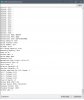
Success! Reading smart battery data

20161226_080821.jpg Screenshot from 2016-12-26 08:27:56.png

Code:
/**********************************

 * SMBus FOR 3DR SOLO
 * STAVROPOULOS
 * Code Version 0.01 beta
 *
 * MUCH OF THIS CODE WAS COPIED FROM
 * https://github.com/PowerCartel/PackProbe/blob/master/PackProbe/PackProbe.ino
 * https://github.com/ArduPilot/PX4Firmware/blob/master/src/drivers/batt_smbus/batt_smbus.cpp
 *
 **********************************/

/**********************************
 * CONFIGURE I2C/SERIAL ON ARDUINO
 **********************************/
 
//DEFINE SDA AND SCL PINS
  #define SCL_PIN 0                 //COMMUNICATION PIN 20 ON MEGA
  #define SCL_PORT PORTD

  #define SDA_PIN 1                 //COMMUNICATION PIN 21 ON MEGA
  #define SDA_PORT PORTD

//CONFIGURE I2C MODES
  #define I2C_TIMEOUT 100           //PREVENT SLAVE DEVICES FROM STRETCHING LOW PERIOD OF THE CLOCK INDEFINITELY AND LOCKING UP MCU BY DEFINING TIMEOUT
  //#define I2C_NOINTERRUPT 1       //SET TO 1 IF SMBus DEVICE CAN TIMEOUT
  //#define I2C_FASTMODE 1          //THE STANDARD I2C FREQ IS 100kHz.  USE THIS TO PERMIT FASTER UP TO 400kHz.
  //#define I2C_SLOWMODE 1            //THE STANDARD I2C FREQ IS 100kHz.  USE THIS TO PERMIT SLOWER, DOWN TO 25kHz.
  #define BAUD_RATE 115200
  #include <SoftI2CMaster.h>

/**********************************
 * CONFIGURE SERIAL LIBRARY
 **********************************/
  //#include <SoftwareSerial.h>
  //#include <Serial.h>
  #include <Wire.h>


/**********************************
 * DEFINE VARIABLES AND SMBus MAPPINGS
 **********************************/
  #define BATT_SMBUS_ADDR                     0x0B                ///< I2C address
  #define BATT_SMBUS_ADDR_MIN                 0x08                ///< lowest possible address
  #define BATT_SMBUS_ADDR_MAX                 0x7F                ///< highest possible address
//BUS MAPPINGS FROM DEV.3DR
  #define BATT_SMBUS_TEMP                     0x08                ///< temperature register
  #define BATT_SMBUS_VOLTAGE                  0x09                ///< voltage register
  #define BATT_SMBUS_REMAINING_CAPACITY       0x0f                ///< predicted remaining battery capacity as a percentage
  #define BATT_SMBUS_FULL_CHARGE_CAPACITY     0x10                ///< capacity when fully charged
  #define BATT_SMBUS_DESIGN_CAPACITY          0x18                ///< design capacity register
  #define BATT_SMBUS_DESIGN_VOLTAGE           0x19                ///< design voltage register
  #define BATT_SMBUS_SERIALNUM                0x1c                ///< serial number register
  #define BATT_SMBUS_MANUFACTURE_NAME         0x20                ///< manufacturer name
  #define BATT_SMBUS_MANUFACTURE_DATA         0x23                ///< manufacturer data
  #define BATT_SMBUS_MANUFACTURE_INFO         0x25                ///< cell voltage register
  #define BATT_SMBUS_CURRENT                  0x2a                ///< current register
  #define BATT_SMBUS_MEASUREMENT_INTERVAL_US  (1000000 / 10)      ///< time in microseconds, measure at 10hz
  #define BATT_SMBUS_TIMEOUT_US               10000000            ///< timeout looking for battery 10seconds after startup
  #define BATT_SMBUS_BUTTON_DEBOUNCE_MS       300                 ///< button holds longer than this time will cause a power off event
 
  #define BATT_SMBUS_PEC_POLYNOMIAL           0x07                ///< Polynomial for calculating PEC
  #define BATT_SMBUS_I2C_BUS                  PX4_I2C_BUS_EXPANSION
//BUS MAPPINGS FROM SMBus PROTOCOL DOCUMENTATION
#define BATTERY_MODE             0x03
#define CURRENT                  0x0A
#define RELATIVE_SOC             0x0D
#define ABSOLUTE_SOC             0x0E
#define TIME_TO_FULL             0x13
#define CHARGING_CURRENT         0x14
#define CHARGING_VOLTAGE         0x15
#define BATTERY_STATUS           0x16
#define CYCLE_COUNT              0x17
#define SPEC_INFO                0x1A
#define MFG_DATE                 0x1B
#define DEV_NAME                 0x21   // String
#define CELL_CHEM                0x22   // String
#define CELL4_VOLTAGE            0x3C   // Indidual cell voltages don't work on Lenovo and Dell Packs
#define CELL3_VOLTAGE            0x3D
#define CELL2_VOLTAGE            0x3E
#define CELL1_VOLTAGE            0x3F
#define STATE_OF_HEALTH          0x4F
//END BUS MAPPINGS
 
  #define bufferLen 32
  uint8_t i2cBuffer[bufferLen];

// standard I2C address for Smart Battery packs
  byte deviceAddress = BATT_SMBUS_ADDR;


void setup()
{

  //INITIATE SERIAL CONSOLE
    Serial.begin(BAUD_RATE);
    Serial.println(i2c_init());

  //SETUP I2C INPUT PINS
    pinMode(43,INPUT_PULLUP);
    pinMode(44,INPUT_PULLUP);
    Serial.flush();

    while (!Serial) {
    ;                                                       //wait for Console port to connect.
    }

    Serial.println("Console Initialized");
 
    i2c_init();                                             //i2c_start initialized the I2C system.  will return false if bus is locked.
    Serial.println("I2C Inialized");
    scan();
}

int fetchWord(byte func)
{
    i2c_start(deviceAddress<<1 | I2C_WRITE);                //Initiates a transfer to the slave device with the (8-bit) I2C address addr.
                                                            //Alternatively, use i2c_start_wait which tries repeatedly to start transfer until acknowledgment received
    //i2c_start_wait(deviceAddress<<1 | I2C_WRITE);
    i2c_write(func);                                        //Sends a byte to the previously addressed device. Returns true if the device replies with an ACK.
    i2c_rep_start(deviceAddress<<1 | I2C_READ);             //Sends a repeated start condition, i.e., it starts a new transfer without sending first a stop condition.
    byte b1 = i2c_read(false);                              //i2c_read Requests to receive a byte from the slave device. If last is true,
                                                            //then a NAK is sent after receiving the byte finishing the read transfer sequence.
    byte b2 = i2c_read(true);
    i2c_stop();                                             //Sends a stop condition and thereby releases the bus.
    return (int)b1|((( int)b2)<<8);
}

uint8_t i2c_smbus_read_block ( uint8_t command, uint8_t* blockBuffer, uint8_t blockBufferLen )
{
    uint8_t x, num_bytes;
    i2c_start((deviceAddress<<1) + I2C_WRITE);
    i2c_write(command);
    i2c_rep_start((deviceAddress<<1) + I2C_READ);     
    num_bytes = i2c_read(false);                              //num of bytes; 1 byte will be index 0
    num_bytes = constrain(num_bytes,0,blockBufferLen-2);      //room for null at the end
    for (x=0; x<num_bytes-1; x++) {                           //-1 because x=num_bytes-1 if x<y; last byte needs to be "nack"'d, x<y-1
      blockBuffer[x] = i2c_read(false);
    }
    blockBuffer[x++] = i2c_read(true);                        //this will nack the last byte and store it in x's num_bytes-1 address.
    blockBuffer[x] = 0;                                       // and null it at last_byte+1
    i2c_stop();
    return num_bytes;
}

void scan()
{
    byte i = 0;
    for ( i= 0; i < 127; i++  )
    {
      Serial.print("Address: 0x");
      Serial.print(i,HEX);
      bool ack = i2c_start(i<<1 | I2C_WRITE);
      if ( ack ) {
        Serial.println(": OK");
        Serial.flush();
      }
      else {
        Serial.println(": -");
        Serial.flush();
      }
      i2c_stop();
    }
}

void loop()
{
    uint8_t length_read = 0;
 
    Serial.print("Manufacturer Name: ");
    length_read = i2c_smbus_read_block(BATT_SMBUS_MANUFACTURE_NAME, i2cBuffer, bufferLen);
    Serial.write(i2cBuffer, length_read);
    Serial.println("");
 
    Serial.print("Manufacturer Data: ");
    length_read = i2c_smbus_read_block(BATT_SMBUS_MANUFACTURE_DATA, i2cBuffer, bufferLen);
    Serial.write(i2cBuffer, length_read);
    Serial.println("");
 
    Serial.print("Manufacturer Info: ");
    length_read = i2c_smbus_read_block(BATT_SMBUS_MANUFACTURE_INFO, i2cBuffer, bufferLen);
    Serial.write(i2cBuffer, length_read);
    Serial.println("");
 
    Serial.print("Design Capacity: " );
    Serial.println(fetchWord(BATT_SMBUS_DESIGN_CAPACITY));
 
    Serial.print("Design Voltage: " );
    Serial.println(fetchWord(BATT_SMBUS_DESIGN_VOLTAGE));
 
    Serial.print("Serial Number: ");
    Serial.println(fetchWord(BATT_SMBUS_SERIALNUM));
 
    Serial.print("Voltage: ");
    Serial.println((float)fetchWord(BATT_SMBUS_VOLTAGE)/1000);
 
    Serial.print("Full Charge Capacity: " );
    Serial.println(fetchWord(BATT_SMBUS_FULL_CHARGE_CAPACITY));
 
    Serial.print("Remaining Capacity: " );
    Serial.println(fetchWord(BATT_SMBUS_REMAINING_CAPACITY));
 
    Serial.print("Temp: ");
    unsigned int tempk = fetchWord(BATT_SMBUS_TEMP);
    Serial.println((float)tempk/10.0-273.15);
 
    Serial.print("Current (mA): " );
    Serial.println(fetchWord(BATT_SMBUS_CURRENT));

    Serial.print("Device Name: ");
    length_read = i2c_smbus_read_block(DEV_NAME, i2cBuffer, bufferLen);
    Serial.write(i2cBuffer, length_read);
    Serial.println("");

    Serial.print("Chemistry ");
    length_read = i2c_smbus_read_block(CELL_CHEM, i2cBuffer, bufferLen);
    Serial.write(i2cBuffer, length_read);
    Serial.println("");

    String formatted_date = "Manufacture Date (Y-M-D): ";
    int mdate = fetchWord(MFG_DATE);
    int mday = B00011111 & mdate;
    int mmonth = mdate>>5 & B00001111;
    int myear = 1980 + (mdate>>9 & B01111111);
    formatted_date += myear;
    formatted_date += "-";
    formatted_date += mmonth;
    formatted_date += "-";
    formatted_date += mday;
    Serial.println(formatted_date);

    Serial.print("Specification Info: ");
    Serial.println(fetchWord(SPEC_INFO));
 
    Serial.print("Cycle Count: " );
    Serial.println(fetchWord(CYCLE_COUNT));
 
    Serial.print("Relative Charge(%): ");
    Serial.println(fetchWord(RELATIVE_SOC));
 
    Serial.print("Absolute Charge(%): ");
    Serial.println(fetchWord(ABSOLUTE_SOC));
 
    Serial.print("Minutes remaining for full charge: ");
    Serial.println(fetchWord(TIME_TO_FULL));
 
    // These aren't part of the standard, but work with some packs.
    // They don't work with the Lenovo and Dell packs we've tested
    Serial.print("Cell 1 Voltage: ");
    Serial.println(fetchWord(CELL1_VOLTAGE));
    Serial.print("Cell 2 Voltage: ");
    Serial.println(fetchWord(CELL2_VOLTAGE));
    Serial.print("Cell 3 Voltage: ");
    Serial.println(fetchWord(CELL3_VOLTAGE));
    Serial.print("Cell 4 Voltage: ");
    Serial.println(fetchWord(CELL4_VOLTAGE));
 
    Serial.print("State of Health: ");
    Serial.println(fetchWord(STATE_OF_HEALTH));
 
    Serial.print("Battery Mode (BIN): 0b");
    Serial.println(fetchWord(BATTERY_MODE),BIN);
 
    Serial.print("Battery Status (BIN): 0b");
    Serial.println(fetchWord(BATTERY_STATUS),BIN);
 
    Serial.print("Charging Current: ");
    Serial.println(fetchWord(CHARGING_CURRENT));
 
    Serial.print("Charging Voltage: ");
    Serial.println(fetchWord(CHARGING_VOLTAGE));
 
    Serial.print("Current (mA): " );
    Serial.println(fetchWord(CURRENT));
 
    Serial.println(".");
    delay(60000);
}
 

Attachments

  • UNOR3SMBus_2.ino.txt
    11.3 KB · Views: 301
  • MegaSMBus_2.ino.txt
    11 KB · Views: 159
Last edited:
EDIT: I AM CURRENTLY USING A PCA9306 LEVEL SHIFTER TO TRANSLATE 5V I2C FROM THE ARDUINO TO 3.3V I2C ON THE BATTERY. THIS IS THE PROPER WAY TO DO THIS AND DOES NOT REQUIRE ADDITIONAL EXTERNAL RESISTORS. SO THE METHOD BELOW WORKS BUT IS NOT RECOMMENDED FOR LONG TERM USE.

To make this compatible with the Arduino UNO R3, you will have to make some changes. The internal pull up resistors of the ATMEGA328PU IC are too large for I2C communications. You will need to disable them and modify the wiring. The 2 changes below are required.:

1. You will need to add a 4.7k-ohm external pull up resistor on each of the SCL and SDA lines. You need to pull the lines up to 3.3 volts (on your arduino).

scl-sda.gif

I believe the reason you don't need to make this change on the Mega 2560 is that it has an internal and an external pull up resistor, and their equivalent resistance is about 5k-ohm. If I recall, the UNO's internall pull up resistor is something like 20k which is not always good for I2C.

2. You will need to change the code as follows:

Code:
  #define SCL_PIN 5                 //Arduino UNO R3???
  #define SCL_PORT PORTC

  #define SDA_PIN 4                 //Arduino UNO R3???
  #define SDA_PORT PORTC


//AND ALSO COMMENT OUT THE PIN MODES
  //SETUP I2C INPUT PINS
    //pinMode(27,INPUT_PULLUP);
    //pinMode(28,INPUT_PULLUP);
 
Last edited:
Here is the code I have been using in my FrankenSolo since last May.
Arduino Nano with an ASC712 current sensor. Measures battery voltage, current & calculates remaining capacity.
It is still a WIP, but works well enough to fly. It assumes that your battery is 5500MAH and is fully charged when you start.
I still plan to estimate starting charge via initial voltage reading and scale as appropriate.

Enjoy... But beware of all issues relating to LiPo batteries. Don't burn down your house or your Solo.
 

Attachments

  • Solo_Batt_Simulator_V3.ino.txt
    22.2 KB · Views: 144
This looks pretty close to the code I'm using.
@pious_greek It looks like there are a few copy/paste errors in the code. Things like:
Serial.print("Temp
no end quote/closing parens)
Serial.print("Chemistry length_read = i2c_smbus_read_block(CELL_CHEM, i2cBuffer, bufferLen);
same thing here + length_read starting


For those who might be getting garbage readings when using the arduino or other system (I'm using Teensy), make sure your arduino gnd and battery gnd are tied together.
 
Thanks Steve, like I said, it was brazenly and gratuitously copied. I couldn't find those errors you mentioned, it seems to be working fine for me, but I'll try to update the code as it evolves if it does. It's just a proof of concept at this point, and might evolve into a charge controller.
 
Thanks Steve, like I said, it was brazenly and gratuitously copied. I couldn't find those errors you mentioned, it seems to be working fine for me, but I'll try to update the code as it evolves if it does. It's just a proof of concept at this point, and might evolve into a charge controller.
They're in the loop() portion.

Edit: it's fine in the downloaded file and the errors are only in the code blocks in the original post.
 
Last edited:
Thank you for posting this!! Great help! Im an arduino noobie and very rusty with my code. @PdxSteve has also been helpful on here! Thank you as well! I have one question that you Arduino master might be able to answer. My SCL/SDA pins are not 0 - 1 like in your code. You define them pretty much right away. Im using an UNO and my SCL pins are A4 and A5 or 16 and 17 it looks like on the PWM side.

When i change the pins in your code Sketch errors and says it has to be less than 8 and positive (my guess it doesn't like the 'A'). If I put in A4/A5.

Arduino Uno Rev3 pinouts photo

Could one of you guys help me in changing the pins so that I can read my batteries as well?

Thank you so much for your time guys!

Cheers!


This is the method and code I used to communicate with the smart battery over I2C with an arduino mega 2560. I was able to communicate over I2C at 5v, but I have ordered a level shifter with the intention of testing if the line works at a safer level of 3.3v as well. Some I2C devices are 5v tolerant, some are not, I really don't know which the solo battery was designed for.

The code is still in beta and much of it was brazenly copied from the references below which @PdxSteve had previously discussed as well.
 
I dont have an UNO, but I'll try to look into it this weekend; i have some atmega328 chips i can put to use.

I think the arduino UNO R3 A4 A5 pins are on pins 4 and 5 of Port C so you'd have to change the code to reflect the following pins and ports:

#define SCL_PIN 5 //Arduino UNO R3???
#define SCL_PORT PORTC

#define SDA_PIN 4 //Arduino UNO R3???
#define SDA_PORT PORTC


//AND ALSO COMMENT OUT THE PIN MODES
//SETUP I2C INPUT PINS
//pinMode(27,INPUT_PULLUP);
//pinMode(28,INPUT_PULLUP);


Arduino UNO R3 Pins 16/17 are PB2 and PB3 respectively, that would be Port B pins 2 and 3.

Give that a shot, if still no luck let me know and i'll see what i can put together.

EDIT: you will need to use 4.7k-ohm pull up resistors to 3.3v
 
Last edited:
  • Like
Reactions: CanadianSolo
wonder if this could lead to a bigger battery on the solo by simulating the communication to solo ?
 
OK so I gave that a go. Its not working, however,
I do have a 16x2 LCD screen that i have been playing with its i2C so i hooked it up to the pins 4 and 5 on PORT C and the i2C scanner at the start found 0x3F which is my screen! So i know that the code is talking to the board and the board is tx and rx on the data lines.

My battery is ON charging. During the scan procedure. its just outputting crap. I do also have my ground from the battery to the UNO.

More help appreciated!!

Thank you @pious_greek


I dont have an UNO, but I'll try to look into it this weekend; i have some atmega328 chips i can put to use.

I think the arduino UNO R3 A4 A5 pins are on pins 4 and 5 of Port C so you'd have to change the code to reflect the following pins and ports:

#define SCL_PIN 5 //Arduino UNO R3???
#define SCL_PORT PORTC

#define SDA_PIN 4 //Arduino UNO R3???
#define SDA_PORT PORTC


//AND ALSO MODIFY THE PIN MODES
//SETUP I2C INPUT PINS
pinMode(27,INPUT_PULLUP);
pinMode(28,INPUT_PULLUP);


Arduino UNO R3 Pins 16/17 are PB2 and PB3 respectively, that would be Port B pins 2 and 3.

Give that a shot, if still no luck let me know and i'll see what i can put together.
 
OK so I gave that a go. Its not working, however,
I do have a 16x2 LCD screen that i have been playing with its i2C so i hooked it up to the pins 4 and 5 on PORT C and the i2C scanner at the start found 0x3F which is my screen! So i know that the code is talking to the board and the board is tx and rx on the data lines.

My battery is ON charging. During the scan procedure. its just outputting crap. I do also have my ground from the battery to the UNO.

More help appreciated!!

Thank you @pious_greek

If you can, add a picture of your wiring and setup just out of curiosity. Do you happen to have a level translator? i ordered one from sparkfun, but it wont arrive for a week or two.

It should find the battery at address 0x08, i think. It sounds like you've got the clock and data lines wired correctly, and your baud rate is set correctly on the serial monitor which would be the most likely culprits if you're getting garbage.

I haven't had a chance to put an atmega328 board together... the only other reason that i can think of for garbage would be the voltage levels. I'm planning to test the voltage translator when it arrives.

if the battery is trying to communicate at 3.3volts the highs might not be high enough to hit the threshold and register as a "1" for the arduino uno that is expecting something close to 5volts for high. it works on the mega 2560 which might have a lower threshold, i'm not sure. Most new chips operate at 3.3volts, and some are tolerant to 5volts which is more of a legacy voltage.
 
Sure thing here. This is my mickey mouse setup for now. Could the BAUD rate between the UNO and battery not be correct?
The Serial output to the screen is just fine. It shows all the fields and the i2C scan and such just all the variables are not correct bogus values. So I know its not talking to the battery pins.

20170101_162112.jpg

If you can, add a picture of your wiring and setup just out of curiosity. Do you happen to have a level translator? i ordered one from sparkfun, but it wont arrive for a week or two.

It should find the battery at address 0x08, i think. It sounds like you've got the clock and data lines wired correctly, and your baud rate is set correctly on the serial monitor which would be the most likely culprits if you're getting garbage.

I haven't had a chance to put an atmega328 board together... the only other reason that i can think of for garbage would be the voltage levels. I'm planning to test the voltage translator when it arrives.

if the battery is trying to communicate at 3.3volts the highs might not be high enough to hit the threshold and register as a "1" for the arduino uno that is expecting something close to 5volts for high. it works on the mega 2560 which might have a lower threshold, i'm not sure. Most new chips operate at 3.3volts, and some are tolerant to 5volts which is more of a legacy voltage.
 
Sure thing here. This is my mickey mouse setup for now. Could the BAUD rate between the UNO and battery not be correct?
The Serial output to the screen is just fine. It shows all the fields and the i2C scan and such just all the variables are not correct bogus values. So I know its not talking to the battery pins.

View attachment 4863

Canadian Solo, I edited my second post above to reflect what changes you will need to make in order to read the smart battery data with an arduino uno.

The arduino uno's internal pull up resistors on the ATMEGA328PU are too large and this can cause issues with I2C communication so you will need to disable those (as indicated in the code changes) and add an external 4.7k-ohm resistors to your circuit instead. See the diagram in post 2.

If you don't have a 4.7k-ohm resistor, anything close to that should work (4k,5k, etc) and depending on what resistors you have on hand, you might be able to combine multiple resistors in series or parallel if needed to get an equivalent resistance close to that.
 
Last edited:
YUP looks like it works @pious_greek. !!!! I got close with my resistors at 4.9kom haha its all i had laying around. Works GREAT!!
I owe you a beer some time man! Now I will be porting some of this info to my LCD screen!! :)

Thanks again for your help!
 

Attachments

  • Success.jpg
    Success.jpg
    118.6 KB · Views: 145
Public service announcement: The level shifter and arduino arrived from sparkfun today and I can confirm that I2C communication works at 3.3v with the smart battery. It's possible the smart battery is 5v tolerant, but until further investigation is conducted I strongly recommend using a level shifter. I'm using the PCA9306. Communication works at 5volts, however without any official documentation stating it is safe, operating at these voltages may reduce the life of smart battery electronics. If you use the a level shifter, you know longer have to use the external pull up resistors. You can think reactivate the internal pullups in the software.

20170107_164952.jpg
 
  • Like
Reactions: Kiraniv Group
Sweet. I have never used a level shifter before? I would have to research what exactly its purpose is for. As for the pull up resistors, I used the 3.3v as my vcc and then used the resistors. Still works. 5v line works too... but I dont like the idea of 5 volts to the battery as you said. 3.3v line on my R3 works!

Question, i have been searching and searching for the battery spade connector. The triple one P/N: 171088-0048. Where did you get yours....? I have found other places on the web but they look shady.

I sourced mine from a dead solo. The triple pin is actually two separate molex ten60 power connectors. The two lower pins are one connector, which is the same that is found on the charger. The one with the data line is a ten60 split.

I think you will have to source each component separately...

Molex RSD-171088-0048.pdf

The level shifter I got from sparkfun: SparkFun Level Translator Breakout - PCA9306 - BOB-11955 - SparkFun Electronics, there are probably cheaper options from china.
 
Last edited:
I have made my own

fairly simple

use a double sided 1/16 copper clad pcb board cut three strips
(optional just for looks) get a small relay take cover off and use cover

solder your wires to both sides on power connector
solder one wire to each side for communication port

take blue painters tape cover battery terminals
slice small slot in tape with razor blade the slide PCB pieces in battery thru cuts in tape

Take JB Weld Putty mold it around connectors slide cover over wait 15 minutes pull out of battery.


IMG_9793.JPG

IMG_9786.JPG


IMG_9798.JPG
 
I have made my own

fairly simple

use a double sided 1/16 copper clad pcb board cut three strips
(optional just for looks) get a small relay take cover off and use cover

solder your wires to both sides on power connector
solder one wire to each side for communication port

take blue painters tape cover battery terminals
slice small slot in tape with razor blade the slide PCB pieces in battery thru cuts in tape

Take JB Weld Putty mold it around connectors slide cover over wait 15 minutes pull out of battery.


View attachment 4937

View attachment 4938


View attachment 4939
why does that plywood have so many holes in it?
 

Similar threads

Members online

Forum statistics

Threads
13,093
Messages
147,741
Members
16,047
Latest member
pvt solo