/**********************************

 * SMBus FOR 3DR SOLO
 * STAVROPOULOS
 * Code Version 0.01 beta
 *
 * MUCH OF THIS CODE WAS COPIED FROM
 * https://github.com/PowerCartel/PackProbe/blob/master/PackProbe/PackProbe.ino
 * https://github.com/ArduPilot/PX4Firmware/blob/master/src/drivers/batt_smbus/batt_smbus.cpp
 *
 **********************************/

/**********************************
 * CONFIGURE I2C/SERIAL ON ARDUINO
 **********************************/

//DEFINE SDA AND SCL PINS
  #define SCL_PIN 5                 //COMMUNICATION PIN 20 ON MEGA PIN5 on R3 UNO
  #define SCL_PORT PORTC

  #define SDA_PIN 4                 //COMMUNICATION PIN 21 ON MEGA PIN 4 on R3 UNO
  #define SDA_PORT PORTC

//CONFIGURE I2C MODES
  //#define I2C_TIMEOUT 100           //PREVENT SLAVE DEVICES FROM STRETCHING LOW PERIOD OF THE CLOCK INDEFINITELY AND LOCKING UP MCU BY DEFINING TIMEOUT
  //#define I2C_NOINTERRUPT 1       //SET TO 1 IF SMBus DEVICE CAN TIMEOUT
  //#define I2C_FASTMODE 1          //THE STANDARD I2C FREQ IS 100kHz.  USE THIS TO PERMIT FASTER UP TO 400kHz.
  //#define I2C_SLOWMODE 1            //THE STANDARD I2C FREQ IS 100kHz.  USE THIS TO PERMIT SLOWER, DOWN TO 25kHz.
  #define BAUD_RATE 115200
  #include <SoftI2CMaster.h>

/**********************************
 * CONFIGURE SERIAL LIBRARY
 **********************************/
  //#include <SoftwareSerial.h>
  //#include <Serial.h>
  #include <Wire.h>
  #include <LiquidCrystal_I2C.h> //i2c library for my LCD display that works.


/**********************************
 * DEFINE VARIABLES AND SMBus MAPPINGS
 **********************************/

  #define BATT_SMBUS_ADDR                     0x0B                ///< I2C address
  #define BATT_SMBUS_ADDR_MIN                 0x08                ///< lowest possible address
  #define BATT_SMBUS_ADDR_MAX                 0x7F                ///< highest possible address
//BUS MAPPINGS FROM DEV.3DR
  #define BATT_SMBUS_TEMP                     0x08                ///< temperature register
  #define BATT_SMBUS_VOLTAGE                  0x09                ///< voltage register
  #define BATT_SMBUS_REMAINING_CAPACITY       0x0f                ///< predicted remaining battery capacity as a percentage
  #define BATT_SMBUS_FULL_CHARGE_CAPACITY     0x10                ///< capacity when fully charged
  #define BATT_SMBUS_DESIGN_CAPACITY          0x18                ///< design capacity register
  #define BATT_SMBUS_DESIGN_VOLTAGE           0x19                ///< design voltage register
  #define BATT_SMBUS_SERIALNUM                0x1c                ///< serial number register
  #define BATT_SMBUS_MANUFACTURE_NAME         0x20                ///< manufacturer name
  #define BATT_SMBUS_MANUFACTURE_DATA         0x23                ///< manufacturer data
  #define BATT_SMBUS_MANUFACTURE_INFO         0x25                ///< cell voltage register
  #define BATT_SMBUS_CURRENT                  0x2a                ///< current register
  #define BATT_SMBUS_MEASUREMENT_INTERVAL_US  (1000000 / 10)      ///< time in microseconds, measure at 10hz
  #define BATT_SMBUS_TIMEOUT_US               10000000            ///< timeout looking for battery 10seconds after startup
  #define BATT_SMBUS_BUTTON_DEBOUNCE_MS       300                 ///< button holds longer than this time will cause a power off event

  #define BATT_SMBUS_PEC_POLYNOMIAL           0x07                ///< Polynomial for calculating PEC
  #define BATT_SMBUS_I2C_BUS                  PX4_I2C_BUS_EXPANSION
//BUS MAPPINGS FROM SMBus PROTOCOL DOCUMENTATION
#define BATTERY_MODE             0x03
#define CURRENT                  0x0A
#define RELATIVE_SOC             0x0D
#define ABSOLUTE_SOC             0x0E
#define TIME_TO_FULL             0x13
#define CHARGING_CURRENT         0x14
#define CHARGING_VOLTAGE         0x15
#define BATTERY_STATUS           0x16
#define CYCLE_COUNT              0x17
#define SPEC_INFO                0x1A
#define MFG_DATE                 0x1B
#define DEV_NAME                 0x21   // String
#define CELL_CHEM                0x22   // String
#define CELL4_VOLTAGE            0x3C   // Indidual cell voltages don't work on Lenovo and Dell Packs
#define CELL3_VOLTAGE            0x3D
#define CELL2_VOLTAGE            0x3E
#define CELL1_VOLTAGE            0x3F
#define STATE_OF_HEALTH          0x4F
//END BUS MAPPINGS

  #define bufferLen 32
  uint8_t i2cBuffer[bufferLen];

// standard I2C address for Smart Battery packs
  byte deviceAddress = BATT_SMBUS_ADDR;

  LiquidCrystal_I2C LCD(0x3B,16,2);


//int i2c;


void setup()
{

  //INITIATE SERIAL CONSOLE
    Serial.begin(BAUD_RATE);
  /*
    Serial.println(i2c_init());


  //SETUP I2C INPUT PINS
   // pinMode(5,INPUT_PULLUP);  // commented this out becauase it cant be used on R3 UNO
   // pinMode(4,INPUT_PULLUP);
    Serial.flush();

    while (!Serial) {
    ;                                                       //wait for Console port to connect.
    }

    Serial.println("Console Initialized");
 */
    i2c_init();                                             //i2c_start initialized the I2C system.  will return false if bus is locked.
    Serial.println("I2C Inialized");


}

int fetchWord(byte func)
{
    i2c_start(deviceAddress<<1 | I2C_WRITE);                //Initiates a transfer to the slave device with the (8-bit) I2C address addr.
                                                            //Alternatively, use i2c_start_wait which tries repeatedly to start transfer until acknowledgment received
    //i2c_start_wait(deviceAddress<<1 | I2C_WRITE);
    i2c_write(func);                                        //Sends a byte to the previously addressed device. Returns true if the device replies with an ACK.
    i2c_rep_start(deviceAddress<<1 | I2C_READ);             //Sends a repeated start condition, i.e., it starts a new transfer without sending first a stop condition.
    byte b1 = i2c_read(false);                              //i2c_read Requests to receive a byte from the slave device. If last is true,
                                                            //then a NAK is sent after receiving the byte finishing the read transfer sequence.
    byte b2 = i2c_read(true);
    i2c_stop();                                             //Sends a stop condition and thereby releases the bus.
    return (int)b1|((( int)b2)<<8);
}

uint8_t i2c_smbus_read_block ( uint8_t command, uint8_t* blockBuffer, uint8_t blockBufferLen )
{
    uint8_t x, num_bytes;
    i2c_start((deviceAddress<<1) + I2C_WRITE);
    i2c_write(command);
    i2c_rep_start((deviceAddress<<1) + I2C_READ);
    num_bytes = i2c_read(false);                              //num of bytes; 1 byte will be index 0
    num_bytes = constrain(num_bytes,0,blockBufferLen-2);      //room for null at the end
    for (x=0; x<num_bytes-1; x++) {                           //-1 because x=num_bytes-1 if x<y; last byte needs to be "nack"'d, x<y-1
      blockBuffer[x] = i2c_read(false);
    }
    blockBuffer[x++] = i2c_read(true);                        //this will nack the last byte and store it in x's num_bytes-1 address.
    blockBuffer[x] = 0;                                       //and null it at last_byte+1
    i2c_stop();
    return num_bytes;
}


void loop()
{


    uint8_t length_read = 0;

    //delay (750);
    Serial.write(12);
    Serial.print("Manufacturer Name: ");
    length_read = i2c_smbus_read_block(BATT_SMBUS_MANUFACTURE_NAME, i2cBuffer, bufferLen);
    Serial.write(i2cBuffer, length_read);
    Serial.println("");

    //Serial.print("Manufacturer Data: ");
   // length_read = i2c_smbus_read_block(BATT_SMBUS_MANUFACTURE_DATA, i2cBuffer, bufferLen);
    //Serial.write(i2cBuffer, length_read);
   // Serial.println("");

   // Serial.print("Manufacturer Info: ");
    //length_read = i2c_smbus_read_block(BATT_SMBUS_MANUFACTURE_INFO, i2cBuffer, bufferLen);
    //Serial.write(i2cBuffer, length_read);
   // Serial.println("");

    Serial.print("Design Capacity: " );
    Serial.println(fetchWord(BATT_SMBUS_DESIGN_CAPACITY));

    Serial.print("Design Voltage: " );
    Serial.println(fetchWord(BATT_SMBUS_DESIGN_VOLTAGE));

    Serial.print("Serial Number: ");
    Serial.println(fetchWord(BATT_SMBUS_SERIALNUM));

    Serial.print("Voltage: ");
    Serial.println((float)fetchWord(BATT_SMBUS_VOLTAGE)/1000);

    Serial.print("Full Charge Capacity mAh: " );
    Serial.println(fetchWord(BATT_SMBUS_FULL_CHARGE_CAPACITY));

    Serial.print("Remaining Capacity mAh: " );
    Serial.println(fetchWord(BATT_SMBUS_REMAINING_CAPACITY));

    Serial.print("Temp: ");
    unsigned int tempk = fetchWord(BATT_SMBUS_TEMP);
    Serial.println((float)tempk/10.0-273.15);

    Serial.print("Current (mA): " );
    Serial.println(fetchWord(BATT_SMBUS_CURRENT));

    Serial.print("Device Name: ");
    length_read = i2c_smbus_read_block(DEV_NAME, i2cBuffer, bufferLen);
    Serial.write(i2cBuffer, length_read);
    Serial.println("");

    Serial.print("Chemistry ");
    length_read = i2c_smbus_read_block(CELL_CHEM, i2cBuffer, bufferLen);
    Serial.write(i2cBuffer, length_read);
    Serial.println("");

    String formatted_date = "Manufacture Date (Y-M-D): ";
    int mdate = fetchWord(MFG_DATE);
    int mday = B00011111 & mdate;
    int mmonth = mdate>>5 & B00001111;
    int myear = 1980 + (mdate>>9 & B01111111);
    formatted_date += myear;
    formatted_date += "-";
    formatted_date += mmonth;
    formatted_date += "-";
    formatted_date += mday;
    Serial.println(formatted_date);

   // Serial.print("Specification Info: ");
   // Serial.println(fetchWord(SPEC_INFO));

    Serial.print("Cycle Count: " );
    Serial.println(fetchWord(CYCLE_COUNT));

    Serial.print("Relative Charge(%): ");
    Serial.println(fetchWord(RELATIVE_SOC));

    Serial.print("Absolute Charge(%): ");
    Serial.println(fetchWord(ABSOLUTE_SOC));

    Serial.print("Minutes remaining for full charge: ");
    Serial.println(fetchWord(TIME_TO_FULL));

    // These aren't part of the standard, but work with some packs.
    // They don't work with the Lenovo and Dell packs we've tested
    Serial.print("Cell 1 Voltage: ");
    Serial.println(fetchWord(CELL1_VOLTAGE));
    Serial.print("Cell 2 Voltage: ");
    Serial.println(fetchWord(CELL2_VOLTAGE));
    Serial.print("Cell 3 Voltage: ");
    Serial.println(fetchWord(CELL3_VOLTAGE));
    Serial.print("Cell 4 Voltage: ");
    Serial.println(fetchWord(CELL4_VOLTAGE));

   // Serial.print("State of Health: ");
   // Serial.println(fetchWord(STATE_OF_HEALTH));

    //Serial.print("Battery Mode (BIN): 0b");
    //Serial.println(fetchWord(BATTERY_MODE),BIN);

    //Serial.print("Battery Status (BIN): 0b");
    //Serial.println(fetchWord(BATTERY_STATUS),BIN);

    Serial.print("Charging Current: ");
    Serial.println(fetchWord(CHARGING_CURRENT));

    Serial.print("Charging Voltage: ");
    Serial.println(fetchWord(CHARGING_VOLTAGE));

    Serial.print("Charging Current (mA): " );
    Serial.println(fetchWord(CURRENT));

    Serial.println(".");


//-----------------------------------------------------
//Attempt to fetch data again and store it for LCD
//-----------------------------------------------------


  float cellV1(fetchWord(CELL1_VOLTAGE));
  cellV1 = cellV1 / 1000;
  float cellV2(fetchWord(CELL2_VOLTAGE));
  cellV2 = cellV2 / 1000;
  float cellV3(fetchWord(CELL3_VOLTAGE));
  cellV3 = cellV3 / 1000;
  float cellV4(fetchWord(CELL4_VOLTAGE));
  cellV4 = cellV4 / 1000;

    LCD.init(); //This initilasies the LCD Screen  This also currently stops the SMBus Battery data reading
    LCD.backlight();//this turns the backlight on


    //LCD.setCursor(0,0);
    //LCD.print("Charge V:");
    //LCD.println(fetchWord(CHARGING_VOLTAGE));
    //LCD.setCursor(0,1);
    //LCD.print("Charge mA:");
    //LCD.print(fetchWord(CHARGING_CURRENT));


    LCD.setCursor(0,0);
    LCD.print("C1:");
    LCD.print(cellV1);
    LCD.print(" ");
    LCD.print("C2:");
    LCD.print(cellV2);


    LCD.setCursor(0,1);
    LCD.print("C3:");
    LCD.print(cellV4);
    LCD.print(" ");
    LCD.print("C4:");
    LCD.print(cellV4);


    delay(100);


}


")


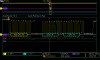
 . Putting a scope on the SMbus revealed a strange thing: the Solo mainboard just makes writes to address 0x00h (data 0x01h 0x00h) - see screenshot attached. This reading is repeated every 2 seconds.