GIMBAL TEARDOWN - SORT OF (and now with some rebuild)

This is not a thorough tear down but rather a glimpse into my experiences with taking apart the Gimbal.

History:
The Gimbal i took apart failed to work properly after a crash from a 2ft height following power failure; my fault, I left RTH too late before percentage of power reached 0 and it dropped heavy to the ground and it tipped over. It didn't think any damage occurred until i powered it back up and the Gimbal failed to respond, producing weird, high pitched sounds. So i purchased another Gimbal and decided to take this one apart to see what damage actually occurred.

Long story short, I found the cause of the failure. When Solo impacted the ground, so did the Gimbal. On doing so, the Gimbal was pushed into Solo forcing the yaw spindle to migrate upwards, moving it out of alignment causing the yaw L shape arm to rub against the Gimbal plate.

This picture shows how the Yaw Motor connects to the Spindle Clasp. This is where it moved. The screws holding it in place weren't strong enough and it moved inwards, moving the whole frame upwards allowing the yaw arm to scrape against the Gimbal Plate. I wish I figured this out before taking the rest apart; it would have been an easy fix. But i commenced tear-down from bottom up rather than top down.

Inside the Clasp is a sneaky screw i missed that secures the screw holding the motor, and upon removing the screw holding the motor i snapped it. Oops. These screws are easily replaced though, but its going to be a challenge removing the remainder from the Clasp.

I think the Yaw motor is damaged too; it doesn't seem to rotate all that smoothly. The Brush-less motors are made by Namiki (part No. S0BL23-1207). Looking at their website, it doesn't appear these motors are available to the consumer market.

View media item 449
View media item 450
View media item 448
This image shows the scrape damage the Yaw arm caused.

View media item 441
I also damaged a ribbon connector on the Gimbal Motherboard too, this is not so easily repaired (I'll have to find someone who can do micro-soldering repairs):

View media item 451
A view from the top of the Gimbal Motherboard:

View media item 452
I wasn't prepared to take everything apart, so these looks a bit messy:

View media item 446
View media item 447
View media item 445
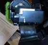
The GoPro Gimabal Cage with the pitch motor removed.

View media item 442
View media item 443
View media item 444
I plan to put this Gimbal together again at some point, but I'm not convinced it will function as before; they may be unseen damage causing problems


Thanks for posting, just what I was looking for.
 
  • Like
Reactions: RichWest
I took mine apart to remove the GoPro connector in order to fix my Xaoimi Yi action cam to it more snugly than it was. I found the ribbon cable from the main board is hard pressed as your photos indicate into the board and can't be unplugged without removing the extra circular board which is inside the arm housing, which was super lame because I threaded the last screw I needed to get off to remove it from the arm, so until I fix that, I can't remove the board - otherwise that would have been grand because I don't have a GoPro but the form factor is the same as the Yi

you can very carefully shave down the plastic of the gimbal that the rubber/HDMI cable wraps around.
 
you can very carefully shave down the plastic of the gimbal that the rubber/HDMI cable wraps around.
Sorry, refresh my mind but what would this help me with and specifically where do you mean?

The issue I believe I was talking about was the GoPro plug needs to be removed, you can't shave this.

Coincidentally since this post, my gimbal has ceased to function properly after it landed abruptly on itself, now it's stuck trying to re-align almost upside down, like the gyro's are all wrong, any ideas?


Maybe it doesnt apply to your situation but toward the top of this link where I and others comment on what seems a similar concern to yours, there is a picture that shows what I was talking about

https://3drpilots.com/threads/gitup-git2-camera-live-view.6910/#post-98925
 

Attachments

  • git2p3.jpg
    git2p3.jpg
    45.1 KB · Views: 63
These are not three phase motors. They are standard brushless gimbal motors and use pulsed DC. The 8313 is a motor driver, like an ESC. The POTs are rudimentary encoders used to determine the position of the motors for better control.
 
These are not three phase motors. They are standard brushless gimbal motors and use pulsed DC. The 8313 is a motor driver, like an ESC. The POTs are rudimentary encoders used to determine the position of the motors for better control.

ok, nice statement - any links to some documents on the used IC´s and Motors from you ?

i´m sure you will read the documents first before posting them here, then you will see yourself that all info you gave is absolutely the opposite of what is really in our gimbals
 
I think that is systematics. There is no AC in a DC brushless motor. There are 3 lines going to the stator in a wye or delta feed but the signal is pulsed DC not AC hence there are no phases of AC current or voltage.

I think the UWV is just identifying the three feed points.
 
oh, man UVW stands for coil U, coil V and coil W
(have a look at page 10 of your linked pdf)
so you agree it is 3 phase now ?

3 phase doesn´t mean it uses AC, who said there is AC anyway ?
phase is not the official name for AC, it means that there is a time shift (120° in 3 phase) of the voltage along all coils

get yourself a H-Bridge and look at the output of it to understand the systematics of this circuit....

(hint: with a H-Bridge you can swap the polarity of each coil to allow CW and CCW rotation of the motor)
 
Last edited:
There is no phase in voltage. These are DC circuits. They are pulsed so they look like square wave flat topped AC but the term phase is indeed referring to a time shift in a sine wave does not pertain to DC. There can be a time shift in a DC pulse train. There are three different legs pulse at a rotating time reference. Like I said semantics.
 
but there is a phase shift in voltage in these DC circuits and it is 120 degree (same as the alignment of the coils in the motor) and it is NOT AC, but there IS a phase shift of 3 DC Signals and the polarity and direction of the shift decides if the motor turns CW or CCW.....

you think that phase has something to do with a AC Sine.... but in real it is a time shift in signals of every shape and it doesn´t matter if it is AC or DC - no one cares about AC or DC when the
time difference and the polarity is what the motors drives CW or CCW.

listen: "phase" is NOT referring to a time shift in a sine wave as you stated !

you have to learn way more than i can write here...... so i´m out of here


Of course but in DC circles it might be called sync or timing. When you use the term "3 Phase" it generally means a 3 phase AC motor. Like I said semantics. Time to put it to bed.
 
  • Like
Reactions: elmatiner0
Amazing- !!!! breaking a few down- be nice to finds schematics or boardviews <----- not sure what entirely opensource gives access to on this- I don't acquire much from anyone but would love to make this one of my knacks for repairing
ANYONE OFFERING FURTHER INFORMATION AND HELP MUCH APPRECIATIONS

THANKS CyBerBLITz
 
Currently, I'm trying to pin point where the problem might be with a "dancing" gimbal I picked up on eBay. At first glance, everything looks in place when compared to my other working gimbal. However, I think this one took a similar hit to the yaw arm, but is very hard to tell. Thanks
 

New Posts

Members online

No members online now.

Forum statistics

Threads
13,094
Messages
147,748
Members
16,058
Latest member
Gabriela