Generic Battery + Arduino = Happy Solo

thanks for chopping:))) chop chop. i like this english word. it remind me of something. chop chop chop.
LM4040 is 1% accuracy. you don't want to use additional voltage reference ic? then it need to pull one pin header from vcc of regulator. let me know.
one single 0805 led consume about 20-25ma. so 160-200ma.
I checked pins out and allocate them as follow.

led1 -> D6, led2 -> D7, led3 -> D8, led4 -> D1, led5 -> D2, led6 -> D3, led7 -> D4, led8 -> D5

then 4 pins(D4,D3,A7,D13) are still available. but one of them(D13) is allocated to builtin led as we know. if you give up builtin led. it is possible to put 4 bits dip switch within board. if not, 3 bits. and pull down is easier to wiring than pull up in this case. need to change code.

about pcb manufacturing, 2 oz is usually 2-3 times more expensive than 1oz. also they have same pricing policy for size out of 100x100mm. so i will try to stay with 1oz and smaller than 100mm.
You could cut down the LED's from 8 to 6. I only used 8 as that was the neopixel board i had. This would save some space and pins.

Have you used D9 for the Neopixel? A 3 DIP switch (or 5 if you dropped a couple of LEDs) would still be useful and leave D13 for the I2C flickering (showing coms working etc). If you turn on the internal pull up resistors in code then the DIP switches only need to be connected to the inputs and ground and no other resistors are needed.

Since the Pro Mini doesn't have an exposed vref then the 5V regulator is all that is needed to power the board and will supply its own reference voltage. I would still use a 1A or higher voltage regulator to make sure its not operating near its max rating.

Even if the 2oz board is twice the price it will make it easier to allow the required current to flow and help get the size of the board down with track size. In the scheme of things this will be a small one-off cost and allow a bit of a safety margin.
 
I haven't been able to find my Pro Mini board so I will have to wait until the ones i ordered arrive and can then test it with my Solo's.
 
You could cut down the LED's from 8 to 6. I only used 8 as that was the neopixel board i had. This would save some space and pins.

Have you used D9 for the Neopixel? A 3 DIP switch (or 5 if you dropped a couple of LEDs) would still be useful and leave D13 for the I2C flickering (showing coms working etc). If you turn on the internal pull up resistors in code then the DIP switches only need to be connected to the inputs and ground and no other resistors are needed.

Since the Pro Mini doesn't have an exposed vref then the 5V regulator is all that is needed to power the board and will supply its own reference voltage. I would still use a 1A or higher voltage regulator to make sure its not operating near its max rating.

Even if the 2oz board is twice the price it will make it easier to allow the required current to flow and help get the size of the board down with track size. In the scheme of things this will be a small one-off cost and allow a bit of a safety margin.
little bit confused. when arduino is starting, aref is vcc(from regulator). no need to do anything if you want to use vcc as vref. but you inserted 'analogReference(EXTERNAL)' in your code. it does mean you are connecting external reference voltage to aref pin. i thought you temporarily connected vcc to vref and change it later. anyway i understand you don't want to use external one. practically it is not any matter. you can leave it blank even if board is designed to have external one.
D9 will be for neopixel. D13 won't be used. regulator will be 1117 with 22uF tant-capacitor. I will consider your offer of removing one or two leds and give spare pins to 4 bits dip switch with internal pull up.
regarding pcb size, 100x40mm is in my mind. may be ok with 1oz. will see.
When i started i was looking to use an arduino nano as it had the usb port for debugging etc. This one had the vref pin exposed so you could provide your own reference voltage and it would use that for the analogue read commands. The Pro Mini board doesn't have this so the analogReference(EXTERNAL) command is not needed and the vref voltage will come internally from the pro mini. In the V3 of the code i have commented this out.

Now just to confuse design matters further......

If you have the arduino at 90 deg (to reduce the board height) the nano is the same height and only 10mm longer, it give easier access to the A4 & A5 pins for I2C and allows for a controlled vref. Then there is also the USB for easier programming.....

1567621583606.png
 
I decided to solder MCU(atmega328) directly to the board. It make everything simple and clear. also it is actually nearer to final destination.

pcb_top_bottom.jpg

dimension.png

- prepared small jumper pad to open/close D10 to led/dip switch. default is open to led. cut jumper trace and solder the other make D10 open to dip switch.

- 8 pcs of single led is 020 SIDE led. not 0805 or 0603 led. refer to BOM.

- 8 leds are connected to D12 - D5.(from right to left on the bottom)

- dip switch is connected to D3,D4,A7,(D10) as a way of internal pull up.

- D9 is supposed to drive Neopixel(or similar digital led strip).

- one i2c connector is prepared.(no pull up resistor)

- one usb/ttl connector is supplied to program atmega328.

- have no idea where to buy solo bat female connector. simplest way is to break solo battery to get it from.


Since arducopter are supporting solo from battery monitor. you can use this board for not only solo but also any with arducopter/4S lipo. i'm planning to add xt60 female connector substitute to solo's one.


<Warning>
1. schematic is very simple but board is little bit picky because of high current. trace width for positive current are designed to endure more than 20A(even for 1oz) but need to strengthen negative one to make thing sure.(especially for 1oz copper pcb) just solder trace or simply connect two point with 14 awg cable.
high_current_soldering.jpg


2. board have never been tested. you can use it but it's at your own risk.

3. traces exposed to air(no mask) is much better to radiate heat. and it is needed for high current. but if you feel uncomfortable. you can use two 2.5mm screw hole to cover board with some 3d printed plate/housing or any other.
 

Attachments

  • bom.txt
    20.9 KB · Views: 24
  • gerber.zip
    183.8 KB · Views: 18
Last edited:
I decided to solder MCU(atmega328) directly to the board. It make everything simple and clear. also it is actually nearer to final destination.

View attachment 10450

View attachment 10451

- prepared small jumper pad to open/close D10 to led/dip switch. default is open to led. cut jumper trace and solder the other make D10 open to dip switch.

- 8 pcs of single led is 020 SIDE led. not 0805 or 0603 led. refer to BOM.

- 8 leds are connected to D12 - D5.(from right to left on the bottom)

- dip switch is connected to D3,D4,A7,(D10) as a way of internal pull up.

- D9 is supposed to drive Neopixel(or similar digital led strip).

- one i2c connector is prepared.(no pull up resistor)

- one usb/ttl connector is supplied to program atmega328.

- have no idea where to buy solo bat female connector. simplest way is to break solo battery to get it from.


Since arducopter are supporting solo from battery monitor. you can use this board for not only solo but also any with arducopter/4S lipo. i'm planning to add xt60 female connector substitute to solo's one.


<Warning>
1. schematic is very simple but board is little bit picky because of high current. trace width for positive current are designed to endure more than 20A(even for 1oz) but need to strengthen negative one to make thing sure.(especially for 1oz copper pcb) just solder trace or simply connect two point with 14 awg cable.
View attachment 10457


2. board have never been tested. you can use it but it's at your own risk.

3. traces exposed to air(no mask) is much better to radiate heat. and it is needed for high current. but if you feel uncomfortable. you can use two 2.5mm screw hole to cover board with some 3d printed plate/housing or any other.
This is great work. How are we supposed to program the MCU?
 
  • Like
Reactions: Professorpip
I decided to solder MCU(atmega328) directly to the board. It make everything simple and clear. also it is actually nearer to final destination.
Another awesome job..... Great idea to add the chip to the board, this was the ultimate plan (may posts back) but i had but just didn't have the know how to do this. Do you have the eagle file to look at your circuit? Did you look at getting the board assembled or have you just ordered all the parts (other than the Solo plug - i know there was talk Molex would do a run for a 1,000. Maybe we could group fund this will still happen and people are interested).

My arduino boards should arrive tomorrow or Wednesday so i will hopefully be able to test them by the end of the week. I know this won't help this design of the board....
 
This is great work. How are we supposed to program the MCU?
Sorry. I forgot to mention about it.
expected problem is bootloader. if you buy a atmega328p mcu. it should be fresh one which you need to burn bootloader yourself. for this, you need usb programmer connect to SPI pins of mcu. after, you can download program through usb/ttl as you are doing now with arduino. but i didn't open SPI pins out on the board as you saw cause this is only one time job and you need to buy extra usb programmer. so here is solution.
buy atmega328p which already have bootloader for arduino ide. or take mcu out of arduino board with heat gun. it is not difficult as you think. just don't forget to heat bottom side of board. mcu won't be damaged at all. don't use your bare hands but some tool like tweezers. besides a price of atmega328 mcu is sometimes more expensive than arduino pro mini. well...

soldering mcu is usually not a piece of cake job for hobbyist like us. but if it is 'atmega328p-au', you could peacefully play with it at one of quiet sleepy night. in compare with other monsters.
 
  • Like
Reactions: Professorpip
Another awesome job..... Great idea to add the chip to the board, this was the ultimate plan (may posts back) but i had but just didn't have the know how to do this. Do you have the eagle file to look at your circuit? Did you look at getting the board assembled or have you just ordered all the parts (other than the Solo plug - i know there was talk Molex would do a run for a 1,000. Maybe we could group fund this will still happen and people are interested).

My arduino boards should arrive tomorrow or Wednesday so i will hopefully be able to test them by the end of the week. I know this won't help this design of the board....
what you need is just buy all parts which are in BOM and also order pcb from manufacturer like JLCPCB or any other. eagle file is not well organized. i am afraid to upload. i will upload in a week. it shouldn't be late because it take time to receive parts and pcb. but actually gerber file have everything what you need.
i ordered parts and pcb yesterday. but they, china will be in the time of holyday this week. it will take longer than ever. hopefully one and half or two week??
1,000 is quite quantity. if such a number want to buy. also crowd funding should be easily possible. i know chinese company who are manufacturing(assembling) various boards.
 
If there is any way to break out some pins or pads to allow usb re-programming it would increase the usefulness and future proofing of this board
 
what you need is just buy all parts which are in BOM and also order pcb from manufacturer like JLCPCB or any other. eagle file is not well organized. i am afraid to upload. i will upload in a week. it shouldn't be late because it take time to receive parts and pcb. but actually gerber file have everything what you need.
i ordered parts and pcb yesterday. but they, china will be in the time of holyday this week. it will take longer than ever. hopefully one and half or two week??
1,000 is quite quantity. if such a number want to buy. also crowd funding should be easily possible. i know chinese company who are manufacturing(assembling) various boards.
Hi hyoo,

I have finally had time to look at my arduino mini pro and hook it up. Unfortunately i spent my time trying to get the driver for my USB to serial adapter working under windows 10 then figuring out when i need to reset the board to start the update process. I now have that sorted i will connect up my solo and battery etc and make sure it all works as expected. I also updated one of my spare solo boards and controller to Open Solo 4.0 so will be able to check it all still works with that.

How did you get on with your latest board?
 
Hi this looks super interesting. Am considering making on of hyoo's boards. Before I send Gerber's to jlcpcb would love to know how well they are working so far?
 
Hi this looks super interesting. Am considering making on of hyoo's boards. Before I send Gerber's to jlcpcb would love to know how well they are working so far?
Hi,

I haven't heard how the latest board design has gone.

Hyoo had an issue with the Pro Mini (with his initial board) so i have finally got back into my shed and in the process of setting up to test this. Hope to confirm that the Pro Mini works as expected.
 
  • Like
Reactions: Professorpip
I have managed to get into my shed and get the Pro Mini programmed (a lot harder than the Nano with its USB port).

The Pro Mini was talking to the Solo and sending battery data through (I had serial monitoring on) but this wasn't being displayed on Solex. I check out and found i hadn't connected up all the GND's. Battery 0V/GND from the Solo, battery 0V/GND and the Arduino GND. After doing this the data was getting through and Solex displayed the battery data.

The filter for the voltage is working well and takes out any jumps in voltage. I am still to test it under load and can adjust the filter. With Open Solo 4 and Solex if you select telemetry it shows the individual cell voltages on the top left.

Hopefully Hyoo can report back how his latest board design went.

I do have the Arduino Pro Mini Eagle file so i could try and design the board myself but this isn't my area of expertise.
 
Last edited:
Hi,

I haven't heard how the latest board design has gone.

Hyoo had an issue with the Pro Mini (with his initial board) so i have finally got back into my shed and in the process of setting up to test this. Hope to confirm that the Pro Mini works as expected.
Thanks for that. I am experimenting with a nano and a pro mini - so will see if I can get it to work
 
I have managed to get into my shed and get the Pro Mini programmed (a lot harder than the Nano with its USB port).

The Pro Mini was talking to the Solo and sending battery data through (I had serial monitoring on) but this wasn't being displayed on Solex. I check out and found i hadn't connected up all the GND's. Battery 0V/GND from the Solo, battery 0V/GND and the Arduino GND. After doing this the data was getting through and Solex displayed the battery data.

The filter for the voltage is working well and takes out any jumps in voltage. I am still to test it under load and can adjust the filter. With Open Solo 4 and Solex if you select telemetry it shows the individual cell voltages on the top left.

Hopefully Hyoo can report back how his latest board design went.

I do have the Arduino Pro Mini Eagle file so i could try and design the board myself but this isn't my area of expertise.
That sounds very positive. I would be very interested to see your latest schematic - I think for my first attempt I will use prototype board / veroboard before making a PCB. I'm going to try making a Li-ion 18650 4s3p pack (which I know has been tried before - and flew ok despite the higher-than-stock weight) - but perhaps this would be the first time using a 'mimic' smart battery, rather than other approaches.
 

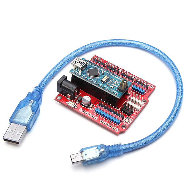
I used this shield to help with connections as there is plenty of 5v and gnd pins to get things working.
 
That sounds very positive. I would be very interested to see your latest schematic - I think for my first attempt I will use prototype board / veroboard before making a PCB. I'm going to try making a Li-ion 18650 4s3p pack (which I know has been tried before - and flew ok despite the higher-than-stock weight) - but perhaps this would be the first time using a 'mimic' smart battery, rather than other approaches.
I am heading down that path. I am currently trying to get my CNC machine working without its current spindle run-out as when cutting a 0.3mm track it ends up over 1 mm and you loose the next track. My other approach may to be use small sections of veroboard for each set of components and then print a 3D holder to put it all together for testing.

At some stage i will look at the eagle design of the mini pro and try and layout a board like hyoo to get made as an all in one (unless hyoo or someone can verify his design works).....
 
  • Like
Reactions: gpang.btr
I was looking online for something and came across this chip.

http://www.ti.com/sitesearch/docs/u...hTerm=ina3221#q=ina3221&t=everything&linkId=1

It measures voltage and current for 3 inputs across a shunt resistor and talks on I2C. I was thinking we could use 2 of these on the board to measure the voltage for each cell removing the dividing resistors and replacing them with the shunt resistor. It looks like they could be independent and just reference the voltage between the each cell rather than having to reference to ground. It could use a software I2C bus as the master for this and the chip can be set to several different addresses.

Arduino Playground - SoftwareI2CLibrary
 
Last edited:
  • Like
Reactions: Linuxcnc69

Members online

Forum statistics

Threads
13,093
Messages
147,741
Members
16,047
Latest member
pvt solo