
Generic Battery + Arduino = Happy Solo
- Thread starter webbs
- Start date

You are using an out of date browser. It may not display this or other websites correctly.
You should upgrade or use an alternative browser.
You should upgrade or use an alternative browser.
- Joined
- Jun 30, 2019
- Messages
- 6
- Reaction score
- 2
- Age
- 52
That is great news. Which Arduino are you using?
I have plans to mount the Arduino and voltage divider on some veroboard this weekend (I always have great plans for my weekends) and see if i can then print a case to hold it.
Webb's,
I am using a Uno compatible. I have a mini that I will program up shortly and probably use on my drone. I have also ordered the neopixel and current sensor.
Regards,
Perry
- Joined
- May 9, 2017
- Messages
- 149
- Reaction score
- 60
- Age
- 51
I am still working through how the final item will look. My voltage regulator has arrived so I will add that to my circuit and test. Once I have done that I can produce a drawing and parts list of my finished concept.Hi, nice project! I always wondered if an Arduino can be used as a bms and there it is! I would appreciate a step by step guide!
I still will have to design and see if I can make a pcb to neatly fit it all together.

- Joined
- May 9, 2017
- Messages
- 149
- Reaction score
- 60
- Age
- 51
I have been doing some brainstorming on how to get to the next phase with a PCB and think i will try and look at using SMD for my circuit. I have priced up the SMD resistors, capacitors and voltage regulator and can get all the bits for about NZ$17 (most are in quantities of 10s or 100s) from RS Components. I have also ordered just the ACS758LCB-050B chip which i plan to include on the PCB (NZ$3.50 each from eBay). With this in mind the circuit board will allow the arduino Nano to be mounted using header pins (or header pins and socket so it can be removed). It should be a single sided board allowing for production on a home CNC etc. I am thinking of powering the voltage regulator from cell 1 and 2 from the balance socket so it will be be close to the 7 volts the regulator needs. If the cell voltages drop below 3.5 each and the regulator stops outputting the solo will stop receiving data and take the voltage as 0V so will carry out its RTL etc.

RS Parts List
820-1598 Balance plugs socket
118-029 10K resistor
119-987 30k resistor
119-965 20k resistor
117-903 1k resistor
648-0941 100nF cap
885-5432 voltage regulator
569-089 22uF cap (voltage regulator)
569-326 10uF cap (voltage regulator)
I will need a couple more components for the current chip circuit if i cant use any of the above.
I just need to find time to get my vision into a circuit then try and arrange a PCB design from that. If there is space i will add some DIP switches to allow for entering a serial number for the battery (so Solex can record data on each battery) and maybe for selecting between different cell types Lipo vs Li Lon so the capacity curve and low limits can be different.
Attachments
Last edited:
- Joined
- May 9, 2017
- Messages
- 149
- Reaction score
- 60
- Age
- 51
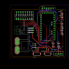
I have had a bit of a play and found i can mount standard resistors under the arduino (if i use header pins and socket) so i have designed a circuit using through hole components.
I have attached the schematic and a PCB layout. There is a lot of work to do on component layout and track arrangement but it all can be done on a single layer board. I might even try and do it with veroboard and wires.
I have changed around some on the analogue pin to allow for easier routing. A4 and A5 are fixed as they are the I2C bus but the rest can be moved around.
I am happy for someone to have a play and come up with a better circuit (i have left out the capacitors for the regulator and current monitor until i get some values for them) and hopefully a more compact PCB layout.
The components i have used are as follows
Voltage Divider
1 * 1k resistor
5 * 10k resistors
1 * 20k resistor
1 * 30k resistor
8 DIP Switch unit (currently i have no code set up to use this but that is the next task - maybe 5 for serial number (32 battery "serial numbers") and 3 for selecting options.
Voltage Regulator
TL780-05KCS (RS Part Number 661-6226)
Current Monitor
ACS758LCB-050B
Headers (JST XH 2.5mm Pitch)
S2B-XH-A I2C Bus (RS Part Number 820-1582) - Anything can be used for this
S3B-XH-A Neopixel (RS Part Number 820-1585) - Anything can be used for this
S5B-XH-A 4S Balance Plug (RS Part Number 820-1598)
Attachments
- Joined
- May 9, 2017
- Messages
- 149
- Reaction score
- 60
- Age
- 51
I have modified the code to include the DIP Switch selections.
1-5 Are for battery serial number. Base number is 32 plus bits from the switch selection (1 2 4 8 16). The Solo then converts the number into a HEX value.
6 Battery Type
7 Battery Capacity Usage
I have also reassigned the pins to match the above circuit.
With the battery type and capacity usage you can set the 100% and 0% cell voltage levels.
The 3rd switch could be used to enable a minimum voltage that is sent back to the Solo to stop RTL based on voltage or any other suggestions.
The new bits in the code are currently untested as i haven't wired up a set of DIP switches yet.
Attachments
- Joined
- May 9, 2017
- Messages
- 149
- Reaction score
- 60
- Age
- 51
I have just found this website
Online curve-fitting at mycurvefit.com
If you input data it produces an equation to map to the data which will give a better result than the linear equation i am using now. Here is an example from some data i found online for a Li Ion battery. If anyone has some data for the Solo Lipo or Li Ion batteries with voltage vs capacity then we can generate an equation for voltage/capacity.
- Joined
- May 9, 2017
- Messages
- 149
- Reaction score
- 60
- Age
- 51
Hi fpvsteve,Depending on the manufacturer, the point of no return (=permanent loss of capacity) of a lipo cell is between 3.0 and 3.3V/cell.
If you trigger failsafe at 13.2V for the entire pack it’s almost guaranteed that one of the 4 cells will drift and go below critical voltage during RTH. Also 14V for the entire pack is too low. I would bet that this is the main cause for dead Solo batteries.
In my RC models and DIY drones I am using battery monitors to control each individual cell and to trigger action once one of the cells goes below 3.6V under load. That’s giving enough of an emergency reserve to return home or to land at a safe place and to keep your batteries alive for many years.
For Solo you can monitor the individual cell voltage in Solex but not trigger a failsafe action. It would be nice if you could add to your project!
I have found this website for generating a formula to fit data points which could be used to generate a more realistic capacity remain % based on voltage.
Online curve-fitting at mycurvefit.com
Do you have some numbers of voltage vs capacity % based on your experience that i could use to generate a formula (incorporating your suggestions above) ?
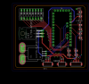
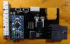
Hello. Here is eagle schematic and board/gerber file from your design. PCB size is 55x63mm.
But I used arduino pro mini instead because of size. It has not AREF pin. so I leave one pin with LM4040. it need to be jumped from pro mini. Just google it. You can find full information to do it.
There are anything to be corrected from files. let me know. I could correct.
I think you have almost finished this project. Hope i will make one for my solo(s!) soon.
Attachments
Last edited:
- Joined
- May 9, 2017
- Messages
- 149
- Reaction score
- 60
- Age
- 51
Thanks hyoo,Hello. Here is eagle schematic and board/gerber file from your design. PCB size is 55x63mm.
But I used arduino pro mini instead because of size. It has not AREF pin. so I leave one pin with LM4040. it need to be jumped from pro mini. Just google it. You can find full information to do it.
There are anything to be corrected from files. let me know. I could correct.
I think you have almost finished this project. Hope i will make one for my solo(s!) soon.
That is a nice layout.
I have Eagle but haven't really used it to produce anything yet.
The LM4040 could be added for a more precise Vref as it has a 1% variation compared to the 2% of the voltage regulator. It looks like the pro mini does have a Vref but not accessible unless you solder directly to the IC.
I looked at the pro mini as it is smaller but is a bit harder to program without the USB plug. Maybe a plug could be added to the circuit for the programming pins to simplify the updating of code if this was the arduino board used.
I was playing with a single;e sided board so i could try and engrave/etch a test one to ensure it all worked as expected before looking to get some boards made. You have come up with a nice small layout ready for production. Do you have plans to get a board made?
- Joined
- May 9, 2017
- Messages
- 1,617
- Reaction score
- 660
- Age
- 46
- Joined
- May 9, 2017
- Messages
- 149
- Reaction score
- 60
- Age
- 51
That will be the ultimate goal. You can even get some of the PCB suppliers to assemble the board which for the surface mount components may be the way to go. The voltage regulator can be replaced by a surface mount one (RS Part number 885-5432) further reducing the space required.JLCPCB anyone?
[And I haven't forgotten your batt webbs. It's in my queue]
Using the Arduino Pro Mini will reduce the size required and if a programming header is added then that would make it simple to program with a USB to serial adapter. I think i will look at writing a calibration program that could be downloaded into the arduino first to work through a procedure to work out the Vref and voltage divider resistor factors. Once you have these factors you can add these to the SMBus code and download it.
That will be the ultimate goal. You can even get some of the PCB suppliers to assemble the board which for the surface mount components may be the way to go. The voltage regulator can be replaced by a surface mount one (RS Part number 885-5432) further reducing the space required.
Using the Arduino Pro Mini will reduce the size required and if a programming header is added then that would make it simple to program with a USB to serial adapter. I think i will look at writing a calibration program that could be downloaded into the arduino first to work through a procedure to work out the Vref and voltage divider resistor factors. Once you have these factors you can add these to the SMBus code and download it.
Hello webbs,
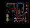
You can connect directly normal(i guess) usb/ttl adapter to pro-mini's upper pin holes. VCC/TX/RX has no problem but different GND position. I personally used to bend GND pin of usb/ttl adapter and jump to pro-mini's. btw I corrected board to have header for usb/ttl adapter for convenience. It could be cut off. and changed connector for bat's balance connector.
The other version of board is dip sw pull-down resistors ver. It maybe live without these. but...
If you choose proper and smaller fancy^^ smd v regulator. It should be much better.
I used to order pcbs from JLCPCB. cheap reasonable quality and faster shipping at least to my country.
Regards
ps: AREF out of pro-mini (see below of this link: Arduino Pro Mini + MMA7361)
Attachments
Last edited:
- Joined
- May 9, 2017
- Messages
- 149
- Reaction score
- 60
- Age
- 51
I have had a though about the coms and could solder a plug directly to the 6 pins on the end of the pro mini so it wouldn't need to be on the circuit board. I have also just used a 6 pin dupont connector and held it at and angle to make a connection to these pins to program it in the past.Hello webbs,
You can connect directly normal(i guess) usb/ttl adapter to pro-mini's upper pin holes. VCC/TX/RX has no problem but different GND position. I personally used to bend GND pin of usb/ttl adapter and jump to pro-mini's. btw I corrected board to have header for usb/ttl adapter for convenience. It could be cut off. and changed connector for bat's balance connector.
The other version of board is dip sw pull-down resistors ver. It maybe live without these. but...
If you choose proper and smaller fancy^^ smd v regulator. It should be much better.
I used to order pcbs from JLCPCB. cheap reasonable quality and faster shipping at least to my country.
Regards
ps: AREF out of pro-mini (see below of this link: Arduino Pro Mini + MMA7361)
I know this will mess up what you have done but i have added in some capacitors to the circuit. I have also added Bat 0V and Bat +V for both the top and bottom of the board and was going to make some large tracks for these.
I have had a play with a layout and still have some work to do with after adding the capacitors. I have the SMD items on the bottom and the plugs and board on the top. I just need to move the Battery balance plug connector a bit to allow a plug to be soldered to the pro mini.
With the DIP switches i would use the internal pull up resistors so they would just need to have a common ground and connected directly to the pins.
Attachments
- Joined
- Jun 30, 2019
- Messages
- 6
- Reaction score
- 2
- Age
- 52
I am having trouble with the cell voltages that are being reported. They are all over the place and the total voltage doesn't match either. What could I be doing wrong. I have used 2 different arduino's and triple checked my wiring. Any thoughts?
Kind regards,
Perry
Kind regards,
Perry
Attachments
- Joined
- May 9, 2017
- Messages
- 149
- Reaction score
- 60
- Age
- 51
The total looks ok but the cells are very strange..... I didn't know you could see the cell info in solex, that will be great for testing.I am having trouble with the cell voltages that are being reported. They are all over the place and the total voltage doesn't match either. What could I be doing wrong. I have used 2 different arduino's and triple checked my wiring. Any thoughts?
Kind regards,
Perry
Are you using a power supply for the arduino or off the USB? This makes a difference and can cause some variation but not 65V.
Also check the resistor setup values in the code (these are what i measured with nothing connected). If the circuit is connected to a battery they change with the battery resistance etc.
//Voltage Divider Resistors values in k ohms
float cell_1_Resistor_1 = 0.998;
float cell_1_Resistor_2 = 18.04;
float cell_2_Resistor_1 = 10.06;
float cell_2_Resistor_2 = 10.11;
float cell_3_Resistor_1 = 19.90;
float cell_3_Resistor_2 = 10.01;
float cell_4_Resistor_1 = 30.01;
float cell_4_Resistor_2 = 10.04;
float vRef = 4950; //mV
Also just check the pins you have connected each cell to is the same as defined in the program as i did move these around when i was working out a circuit layout.
//Pins for Reading Voltage
int pinCell_1 = A0;
int pinCell_2 = A1;
int pinCell_3 = A2;
int pinCell_4 = A3;
//Pins for Reading Voltage
int pinCell_1 = A6;
int pinCell_2 = A3;
int pinCell_3 = A2;
int pinCell_4 = A1;
If this doesn't help then you might need to add some debugging with serial printing so you can see what the arduino gets at each step of the voltage reading.
Add to the Setup
Serial.begin(9600);
Then in the code add serial print lines, like below. This is what i did when setting up the code to get it right.
//Read Voltage and Current from Analogue Inputs
//Cell 1
float cell_temp = float(analogRead(pinCell_1));
Serial.print("Cell 1 read = ");
Serial.println(cell_temp);
cell_temp = cell_temp * (vRef/1023);
Serial.print("Cell 1 Raw Voltage = ");
Serial.println(cell_temp);
cell_temp = cell_temp * ratioCell_1;
Serial.print("Cell 1 Ratio = ");
Serial.println(ratioCell_1);
cell_1 = int(cell_temp);
Serial.print("Cell 1 Voltage = ");
Serial.println(cell_1);
- Joined
- Jun 30, 2019
- Messages
- 6
- Reaction score
- 2
- Age
- 52
Webbs,
Thanks so much for your fast response. I will check all of that and let you know how I go.
Cheers,
Perry
Thanks so much for your fast response. I will check all of that and let you know how I go.
Cheers,
Perry
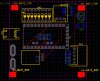
PCB was arrived days ago. I assembled parts to the board tonight. This is renovated design which can be directly connected to solo. used salvaged battery connector from solo's and XT60.
Result of test is not so accurate though i used LM4040(4.57 calibrated voltage). should feed voltage divider some capacitors to remove noise.
Neopixel is unnecessarily bright and big in this small application. I became to think this is not appropriate option. better to remove this giant led/dip switch and add 0805 normal single color leds to the top of board instead. I guess.
I will upload gerber file after modifying and testing.
Attachments
Similar threads
- Replies
- 1
- Views
- 2K
- Replies
- 6
- Views
- 4K
- Replies
- 1
- Views
- 2K
- Replies
- 8
- Views
- 3K
New Posts
-
 Free Music / SFX Resource for Your Videos - Over 2000 Tracks
- Latest: Eric Matyas
-
-
-
-