

- Joined
- May 9, 2017
- Messages
- 149
- Reaction score
- 60
- Age
- 51
Truly awesome!
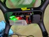
Great idea to add solo plug to the board and the xt60 plug.
The neopixel brightness can be adjusted in the code. I know on the ground it is very bright but was thinking in the air it would be ok. Also I thought I would use a lead and mount it under or on the back of the solo.
I haven't seen any voltage dividers with caps on them but they could help. We could also introduce a filter into the code to smooth out some of the noise.
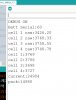
Is the 4.57V enough to power the arduino?
The dip switch was to allow for some selection including a serial number for the battery so Solex can keep track of the batteries used.
Let me know if you are happy to mod the code for the brightness and filtering the voltage values otherwise I will have a look.
Great work and some great improvements to the board design.
Great idea to add solo plug to the board and the xt60 plug.
The neopixel brightness can be adjusted in the code. I know on the ground it is very bright but was thinking in the air it would be ok. Also I thought I would use a lead and mount it under or on the back of the solo.
I haven't seen any voltage dividers with caps on them but they could help. We could also introduce a filter into the code to smooth out some of the noise.
Is the 4.57V enough to power the arduino?
The dip switch was to allow for some selection including a serial number for the battery so Solex can keep track of the batteries used.
Let me know if you are happy to mod the code for the brightness and filtering the voltage values otherwise I will have a look.
Great work and some great improvements to the board design.

 )) chop chop. i like this english word. it remind me of something. chop chop chop.