Compact Solo Extremely slow worklog

Joined
Apr 26, 2017
Messages
35
Reaction score
26
Age
37
Greetings! And welcome! ;-)

I already wrote a couple of times in different threads about my sluggish project of a compact solo and decided to start my own thread.
I bought a year ago electronics and controller from solo on ebay

photo_2017-06-02_15-11-49.jpg

and planned to make a clone of Mavic, but the lack of time and complexity with the embedding of a solo in a small frame slowed me down.
photo_2017-04-15_15-36-14.jpg photo_2017-04-15_15-36-17.jpg photo_2017-09-23_13-15-07.jpg


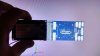
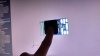
At the moment I have already cut off most of the board from solo,
photo_2017-06-08_22-59-59.jpg photo_2017-06-08_23-00-02.jpg photo_2017-09-23_17-44-39.jpg

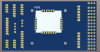
but for me it's still too big, so I decided to make my carrier board. This is the first time I've done this, so the board is not perfect, but there are only two layers, so you can order it in China very cheaply.I called it Simple as F ... SOLO_PXHWK2_CARRIER. on it there is not one active component except the native power module from the solo (I was thinking of adding a few transistors for the level converter, but I most likely use uavcan node from olliw, maybe later in version B I will do it), it is slightly larger than the board from proficnc. 85x45mm. I'll order the boards and test it soon
Снимок (1).PNG

Gerber:
Saf_CARRIER.zip — Yandex.Disk
Schematics:
00-59.PDF — Yandex.Disk

I decided to use Olliw's uavcan for escs, so the problem with 3.3 volts does not threaten me.

In the future, I want to try to make my own compact folding frame design, a micro gimbal with a camera (a lens in the gimbal, a board in the drone)
photo_2017-07-05_15-46-59.jpg photo_2017-07-05_15-46-53.jpg

and I also dream of reducing the size of the controller ... so this is a very long project

I will be glad to your ideas and advice
 
Last edited:
I hope that I did nothing incredibly dumb while I was tracing my first board.
 

Attachments

  • photo_2018-02-23_00-38-27.jpg
    photo_2018-02-23_00-38-27.jpg
    103.4 KB · Views: 91
  • photo_2018-02-23_00-38-36.jpg
    photo_2018-02-23_00-38-36.jpg
    102 KB · Views: 90
  • Снимок.PNG
    Снимок.PNG
    71 KB · Views: 91
  • мок.PNG
    мок.PNG
    313 KB · Views: 94
  • Like
Reactions: jonbrotherton
If you are going to re-design the Solo, you might want to investigate a different Companion Computer.
This looks interesting: Emlid Neutis
iMx6 hardware is somewhat outdated and vastly overpriced for what you get. Needless to say that their (NXP's) support for modern kernels is somewhat lacking. Good VPU/IPU/GPU support from third parties like GateWorks though. So don't count them (NXP) out.
 
  • Like
Reactions: Saijin_Naib
If you are going to re-design the Solo, you might want to investigate a different Companion Computer.
This looks interesting: Emlid Neutis
iMx6 hardware is somewhat outdated and vastly overpriced for what you get. Needless to say that their (NXP's) support for modern kernels is somewhat lacking. Good VPU/IPU/GPU support from third parties like GateWorks though. So don't count them (NXP) out.
Hmm, I do not think that I want to change the sololink to something else. If so, I will need to think about videolink and if for rc and telemetry I can use the new open source qlrs link, then the video is more complicated. One of the purposes of my project is to spend as little money as possible, if I wanted to spend money, it would be easier to buy a Mavic I think.
 
Video is always complicated, even on the Solo. After looking more carefully at the Emlid Neutis, I realized it is (probably) their home grown (maybe) replacement for the Intel Edison used in their Reach and Reach RS product. Emlid also has a flight controller, Edge, so Neutis is the logical progression in their product line.
I have no association with Emlid and don't use their products, I just thought it was an interesting product with some potential for use as a Companion Computer.
 
I'm back. I ordered 10 boards in China here (10 for the price of one)! It's cool!

For order, I sent them these files

The production costs only 5 bucks, but they give everyone a $ 5 coupon for the first order, so I only paid $ 9 for shipping. It's awesome! I could follow the progress on their website, the production lasted only two days, so now I'm waiting for the delivery of my order. This Chinese service is something incredible.

I also ordered several df17 connectors at the local store, they should come in a week or two. And while I'm waiting I unsolder PSM module from the board. Here are a couple of photos, if anyone is interested.

IMG_20180317_174536_HDR.jpg IMG_20180317_174549_HDR.jpg
 
  • Like
Reactions: MrSteal
Uh ... it was fun...
And no magic smoke and sparkles! :)
To view this content we will need your consent to set third party cookies.
For more detailed information, see our cookies page.

IMG_20180322_221158.jpg IMG_20180322_225503.jpg IMG_20180322_230951.jpg IMG_20180322_232508.jpg IMG_20180323_000718_HDR.jpg
 
  • Like
Reactions: Ed.it.Ed
Nice work, wish you much success with your project.
Thank you very much! I hope that I will not fail miserably in the end. :)
Tomorrow I'll try to solder the connectors and start thinking about the frame. It's good that I have both a CNC router and a 3d printer now, so it will be much easier and more fun.
 
I envy you young guys with cnc anything...really exciting tools to have. I watch NYC CNC and others all the time...I love that stuff.

Measure twice, cut once....
 
  • Like
Reactions: carpy
I envy you young guys with cnc anything...really exciting tools to have. I watch NYC CNC and others all the time...I love that stuff.

Measure twice, cut once....
Yeah! What a great time to be alive!
I love all these new technologies and CNC and 3D printers. I like that it is becoming more affordable and cheaper. My grandfather and father worked all their life with wood and furniture, and I quickly got bored up with all of it in my childhood, I was more interested in new technologies and computers ... and here I am 15 years later I combine work with wood and computers. ;-)

I've been working as a CNC technician for ten years,
To view this content we will need your consent to set third party cookies.
For more detailed information, see our cookies page.

now I'm on a more creative job

DSC_7099.jpg DSC_7097.jpg
 
Wow, it appears you have the knack...nice woodwork. Seems you had good role models, I bet you're glad they never pulled that splinter....;)
 
Ok. It's actually works. Not just turning on, lol.
I'm out of connectors at home. I searched in all my electronic junk and found nothing, I will need to buy a couple more. And i'm definitely need good soldering iron, not that old burned piece of crap that i have now.

photo_2018-03-24_16-33-46.jpg photo_2018-03-24_18-38-23.jpg photo_2018-03-24_18-46-32.jpg photo_2018-03-24_18-46-42.jpg

And by the way, if you want to go even further in simplifying the carrier board, then I assume that you can drop the psm module by feeding power to the FMU_5VA pad directly, in order to work it is necessary to give 3.3 V. on the pad next to it.
Well, and of course you have to feed the whole periphery separately on pins in a blue circle.
Снимок.PNG

By doing this you lose all this fancy schmancy functionality that this module gives, such as filtering, protection, etc., as well as the buzzer driver

Correct me if I'm wrong
 
Last edited:
Question: What was the reason you didnt just use the github pcb schematic for the Prolific carrier board? On the surface it seems like it might have been a path of less resistance with a more certain result.
 
Question: What was the reason you didnt just use the github pcb schematic for the Prolific carrier board? On the surface it seems like it might have been a path of less resistance with a more certain result.
Firstly, it's boring, and secondly, I do not know :) (In fact, the original board has 4 layers so it costs more in production, and all the necessary outputs for sololink are allocated to connect the Intel Edison and routed to different connectors. Very inconvenient)

Flight tests will not be soon, it's an extremely slow worklog after all. Now I'll finish with the carrier board and want to do something with the remote control and I need to think about the frame too.
 
Last edited:
  • Like
Reactions: MrSteal
And by the way, if you want to go even further in simplifying the carrier board, then I assume that you can drop the psm module by feeding power to the FMU_5VA pad directly, in order to work it is necessary to give 3.3 V. on the pad next to it.
Turns out it works even without feeding 3.3v to valid! pins. A friend of mine tested this. All you need is to connect one of the power inputs with the fmu input(Blue). And optionally also connect the outputs to power the periphery (Red). But it's like swimming without swimming trunks in the pool with piranhas. All protection and filtering will be on you and your power source.
And ProfiCNC guys will probably hate me for that. But this is your money and your hardware, and you can do with it whatever you want, if you do not ask for warranty repair after that, of course.
Снимок.PNG
 
Last edited:

Members online

No members online now.

Forum statistics

Threads
13,093
Messages
147,741
Members
16,048
Latest member
ihatethatihavetomakeanacc