
Solo Breakout Board & connectors
- Thread starter cynfab
- Start date

You are using an out of date browser. It may not display this or other websites correctly.
You should upgrade or use an alternative browser.
You should upgrade or use an alternative browser.
- Joined
- May 9, 2017
- Messages
- 1,617
- Reaction score
- 660
- Age
- 45
Is this what you need?Maybe you guys can help. I am trying to find out the pin setup for the ribbon cable for the accessory port. I've posted this request in many places but no help had come.
Accessory Bay | 3DR Solo Development Guide
This is for the accessory connector. I'm looking for the pin out of the ribbon cable to the main board inside.Have you checked the Accessory Bay development guide? As I recall there is a pinout there.
Thanks for your trying to help. It's much appreciated.
- Joined
- May 9, 2017
- Messages
- 1,617
- Reaction score
- 660
- Age
- 45
You could easily use a Meter and that Pinout to determine the pinout on the other end.This is for the accessory connector. I'm looking for the pin out of the ribbon cable to the main board inside.
Thanks for your trying to help. It's much appreciated.
The only ribbon connector inside solo is for the accessory bay.
Unfortunately I broke the cable from the main board so I can't meter it out.
Is it that impossible to get a schematic or pin out diagram. Am I asking for something that isn't available. I thought this would be something that would be available. So many people have been really helpful and I appreciate all the hard work and ideas.
Is it that impossible to get a schematic or pin out diagram. Am I asking for something that isn't available. I thought this would be something that would be available. So many people have been really helpful and I appreciate all the hard work and ideas.
- Joined
- May 9, 2017
- Messages
- 1,617
- Reaction score
- 660
- Age
- 45
Wow thank you. This is much closer to what I need. I broke the connection of the ribbon cable from the main board to the accessory board at the main board side. I think with this and a bit of looking around the site y you found it on I will be able to fix the issue. Thank you so very much.
I haven't tried to solder my guess on how it should be. Before I hear up the de-soldering and the soldering irons I'm going to ask one more time.
Does a schematic or wiring diagram exist?
I know most people will never need either of these. It would be nice to have since every other aspect of this drone is open source, shouldn't these documents be part of it all?
Maybe somebody that is reading this might know someone or somehwere that these things are locate.
Thank you all for the help with this issue. This is how the world should be, those that can help do and teach those that don't so that They can help others.Thsnk you all again.☺
- Joined
- May 9, 2017
- Messages
- 1,617
- Reaction score
- 660
- Age
- 45
I *really* don't know what else you want provided. Pinouts for both ends have been linked. The mainboard and accessory pcb are both numbered 1-23. The ribbon cable is so short it can only connect in one orientation. And I'm willing to bet there are still bits of wire sticking thru the pcb on whichever end broke off. I'm flummoxed what other info you could need for this....
But, I've been known to be dense before.....
So what *EXACTLY* is it that you are looking for again?
But, I've been known to be dense before.....
So what *EXACTLY* is it that you are looking for again?
Hello just_bruce
Thank you for your patients and understand. I'm the one that is flummoxed.
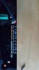
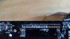
My problem is that when I look at the main board connection there are numbered solder points. Under close inspection, I have determined thsy the first 15 pointsvhave some sort of solder on them. It appears that points 1 & 2 are soldered together, leaving points 3 to 15 left with solder. So I don't know if I should solder 1-13 or 3-15. I have attached pics for you to help me decide what points the cable should be attached.
Thank you for your patients and understand. I'm the one that is flummoxed.
My problem is that when I look at the main board connection there are numbered solder points. Under close inspection, I have determined thsy the first 15 pointsvhave some sort of solder on them. It appears that points 1 & 2 are soldered together, leaving points 3 to 15 left with solder. So I don't know if I should solder 1-13 or 3-15. I have attached pics for you to help me decide what points the cable should be attached.
- Joined
- May 9, 2017
- Messages
- 1,617
- Reaction score
- 660
- Age
- 45
Points 1 and 2 are VBat. They still each get their own connection, as that is the way the battery voltage is kept stable. Connect 1-15 to their correspondent on the other end.
Thank you for your input. There are only 13 points on the ribbon cable and the go to points 1-13 on the accessory board.
So if I go ahead and connect 1-13 on the main bo10309"]Hello just_bruce
Thank you for your patients and understand. I'm the one that is flummoxed.
My problem is that when I look at the main board connection there are numbered solder points. Under close inspection, I have determined thsy the first 15 pointsvhave some sort of solder on them. It appears that points 1 & 2 are soldered together, leaving points 3 to 15 left with solder. So I don't know if I should solder 1-13 or 3-15. I have attached pics for you to help me decide what points the cable should be attached.[/QUOTE]
Points 1 and 2 are VBat. They still each get their own connection, as that is the way the battery voltage is kept stable. Connect 1-15 to their correspondent on the other end.
Attachments
Hello
Thanks again for your help. There are only 13 points on the ribbon cable. These are connected to 1 to 13 on the accessory board. So if I go ahead and connect the ribbon cable to 1 to 13 on the main board this should be the answer?
Thanks again for all of you time and energy with this flummoxed noob. I also appear to not be able to use this forum, but I did upload two pics and they went somewhere. I hope you can find them .
Hello
Thanks again for your help. There are only 13 points on the ribbon cable. These are connected to 1 to 13 on the accessory board. So if I go ahead and connect the ribbon cable to 1 to 13 on the main board this should be the answer?
Thanks again for all of you time and energy with this flummoxed noob. I also appear to not be able to use this forum, but I did upload two pics and they went somewhere. I hope you can find them .
I understand being flummoxed. Spent a bit of time on this myself yesterday. The pins from the mainboard/ribbon are not numbered the same as the accessory bay board. I was not able to fully map the differences.
If all you're doing is replacing a broken cable, resolder 1-13 to 1-13...
Thanks for the input at 7:00 am. I will try to do the connections from 1-13. But then I have to ask what are 14 and15 on the main board soldered to?
I feel more inclined to use pins 3 -15 because it looks like 1 and 2 are soldered together
But then 1 and 2 ate power as has been suggested. So I am still confused.
If anybody currently has their SOLO apart could you please take a look and maybe send s pic, highlighting the ribbon cable's connection to the main board o really want to get this right, and not fry anything
Thank you all and thanks to the forum community l would be lost without this place.
Thanks for the input at 7:00 am. I will try to do the connections from 1-13. But then I have to ask what are 14 and15 on the main board soldered to?
I feel more inclined to use pins 3 -15 because it looks like 1 and 2 are soldered together
But then 1 and 2 ate power as has been suggested. So I am still confused.
If anybody currently has their SOLO apart could you please take a look and maybe send s pic, highlighting the ribbon cable's connection to the main board o really want to get this right, and not fry anything
Thank you all and thanks to the forum community l would be lost without this place.
http://i60.tinypic.com/rlbc4k.jpg
Similar threads
- Replies
- 0
- Views
- 1K
- Replies
- 9
- Views
- 5K
- Replies
- 15
- Views
- 5K
- Replies
- 18
- Views
- 7K
New Posts
-
 Free Music / SFX Resource for Your Videos - Over 2000 Tracks
- Latest: Eric Matyas
-
-
-
-
