I'm building a car charger & I've got a question

Joined
Oct 24, 2015
Messages
22
Reaction score
8
Age
48
Since most of my flying is closer to my car than a 120 V wall socket, I’ve built a 12V car charger for my Solo. My goal for this charger is to be able to charge at least one, possibly more batteries, without hearing the constant buzz that my power inverter makes.

I'm using one of these from amazon:
Amazon.com: DROK® 600W 12A DC Boost Voltage Converter 12-60V to 12-80V Step-up Power Supply Transformer Module Regulator Controller Constant Volt/Amp Car Regulated Laptop Battery Charger LED Driver Generator: Electronics

This is a variable output 12V DC-DC boost circuit with adjustments for max current and set voltage. The 600W in the description is misleading as it’s limited to 10 amps without a fan, so 10 amps at 60 V is 600W, but 10 amps at 12V is only 120W. Pay no attention to the review that says that you can’t adjust the current, they were wrong (or maybe I got lucky). The same circuit is available from several manufacturers, this is just the one I happened to pick.

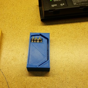
I’ve cut my 3DR power supply cord and added an XT60 connector to it and to the DC power supply so I can move the plug from one to the other. Using a dummy load I’ve set the voltage at 16.8 V and the max current at 3.5 amps. I’ve plugged in a Solo battery to make sure it works--it does. In my minimal testing, it works great. At either 12 or 14.5 volts in, the power supply held its output steady at 16.80 volts. The heat sink barely got warm. And while I haven’t tested it for efficiency yet, I expect that it's about 85% or 90% efficient in this application (these circuits are more efficient when the in and out voltages are close to each other).

My question is this: What is the current limit that the “smart battery” circuitry charges at? I understand that the charger from 3DR is just a plain old 16.8 V, 3.3 amp wall-wart with nothing fancy going on, so the battery can’t charge itself with more than 3.3 amps with that charger. I also understand that it’s “smart” because it can control the rate a various charge levels of the battery. But it wouldn’t be very “smart” if it allowed me to throw 10 or 20 or 50 amps at the battery, so I would think that the battery has some sort of over-current protection.

I’d like to know if I set the power supply to 10 A to be able to charge multiple batteries at once, and there is only one battery connected, will that battery limit itself to say 1 C, or will it let itself take it all in?
 
  • Like
Reactions: MachWun
You can't really force feed something amperage unless there's a short circuit. The charger in the battery pack will only draw what it needs. So set the amperage to 6a for 2, 9a for 3 and 12a for 4. this is a great idea by the way. I wish there was a more refined plug solution though. Not something hacky for the other 3

Sent from my SM-G928T using Tapatalk
 
Great, Thanks!

I understand that's how it works with resistive loads, but I thought it was different when it comes to charging batteries.

I took advantage of the 20% coupon around new years and bought two additional chargers. It's kind of an outrageous price to pay for what you're getting, but I'll now be able to charge 3 at once at home or on the go. I've got 4 batteries now, so if I can charge 3 at once, I'll pretty much be able to play all day (as long as I keep my car's engine running ;)
 
Why wouldn't you buy a 29 dollar inverter from Walmart and go that way?
 
Why wouldn't you buy a 29 dollar inverter from Walmart and go that way?
Because you will still need the solo wall warts. He is bypassing the entire wall wart and will feed direct power into the pack

Sent from my SM-G928T using Tapatalk
 
Why wouldn't you buy a 29 dollar inverter from Walmart and go that way?
Two reasons actually. As MachWun said, I'm bypassing quite a bit of inefficiency. Using an inverter you go from 12VDC >> 120VAC >> 16.8 VDC, this way I'm going straight from 12VDC >> 16.8VDC, and using less of my car battery to do it. Secondly, I already have the $29 inverter and it's a noisy little thing. The power supply I'm using is fanless.
 
hi guys, I'm also trying to build a multi port charger/docking station with at least three docks for charging the 3dr solo battery. mainly with a source voltage of 12V, so that I can plug it in the car, and also plug on the wall outlet with the use of a power adapto so that I can plug it in the car, and also plug on wall outlet with the use of a power adapter. I have four batteries and it would be lovely to charge at least three of them at the same time ( Full speed, 3.3amps like the original charger) in the car in my upcoming vacation west coast.

I have ordered a power converter DC to DC, a 12 V to 17v with the maximum amperage output of 10amps on the 17V side. I just got them last night, and did a rough test. I measured the output voltage with a digital voltmeter, and luckily my 17 V, is outputted 16.6-16.8v which is about the same as the solo original battery charger. note*: I have read everywhere in the forums regarding using 3rd party chargers, and they all have the same experience, in that all their third-party chargers you need to turn the solo battery on( just like you turn on the quad copter, hold the button until lights cycle and turn on) before the battery starts charging. The DC to DC converter I have, I tested it. and charging one battery, with the 10 amp available power from the supply, The battery behave exactly like the original charger ( in that I don't have to turn the battery on like the other many users have to ) it turns on by itself and starts charging.

before I started this project, i've been thinking what possibly 3DR, have implemented regarding the automatic turning on of the battery when plugging in the charger with using only the two prongs the positive lead and the negative lead. there's no data lines or anything else. at One point I even thought they incorporated some AC signal on both the positive and negative terminals. I just found out by trying my DC to DC converter, The battery is just actually looking for the perfect source voltage (16.6-16.8v) to trigger the automatic turning on when connecting a power source to the battery.

I haven't made the whole circuit complete yet because there's one thing I am facing right now, if I charge three batteries at the same time everything goes well with the 10amps supply.(10amps gets divided equally by 3x 3.3amps battery load) but if I charge only one battery, I measured each batteries amperes going through the positive and the negative terminals. it reads about 5amps+ at first and then charge cuts off for 3 seconds and batteries turn off, and AUTO wakes and charge again for probably 10 seconds and again and again. and also I tried to put a 5a automotive DC fuse before the positive terminal going to the battery, and charging of one battery goes perfectly well just like the original solo charger. I know these batteries are rated 3.3amps charging, and from all the forums I read, they all say you cannot push more than 3.3 A, but it sure does accept 5.5amps at first then taper down to 3.5amps after a few minutes.

so my next step now is to, find a DC current limiter chip/ic (or build a custom circuit) to limit the current going to each charging port to 3.3amps very close to the stock solo charger ( i've been doing my calculations with the Circuit that I am about to make, and my output would be about 3.7amps), and everything should work well. now I'm off to the electronic store, near my workplace.

and after this I will make a contraption, from scratch, where in I can just dock 6 solo batteries for charging on the unit/docking station. (i have 2 of the 17v 10amps dc-dc converter), so it can handle 6batteries at a time (at full oem speed charging).

wish me luck with success on this project. I know a lot of guys, wanting to build the same thing. a multi battery charger for their x number amount of solo batteries and having only 1 or 2 chargers.

ps, I'm and electronically inclined person. my dad is an electrical engineer, so i get all the support

-jeffrey p
 
You don't want a dc-dc converter which only provides constant voltage (most regular power supplies). You want a dc-dc cc/cv (constant current, constant voltage) converter. You can push a max of 6A into the battery, but anything higher will cause the battery to turn off and back on and it will just continually power-cycle. You will also need one converter per battery, but they only cost about $13. You can't charge them in parallel like you were trying because as you mentioned, as the battery charges the amps drop, which pushes higher amps into the other remaining batteries since there is no ability to limit the current. Once that threshold hits above 6A, the remaining batteries will start power cycling and not charging. So you need one converter per charger.

I have a 6 battery charger working that also has a charger for the controller as well as (2) 3.1A USB fast-charging ports, all hooked into an arduino showing battery levels and other extended battery info from the data port on the battery.
 
@PdxSteve response should become the standard answer to battery questions, he has done some good research here.
I cant believe some people still think the 3.3 amp Solo charger is a wall wart, some basic testing will show it IS a 4S lipo charger
Good work @PdxSteve
 
@PdxSteve has done an outstanding job on the charging system. Well Done Steve..
I bet he could design a tray that will plug in where the battery goes that will allow a larger battery? Use a velcro system and XT connectors/balance plugs to feed info to the FC. What do you say Steve?
 
  • Like
Reactions: PdxSteve
@PdxSteve has done an outstanding job on the charging system. Well Done Steve..
I bet he could design a tray that will plug in where the battery goes that will allow a larger battery? Use a velcro system and XT connectors/balance plugs to feed info to the FC. What do you say Steve?
Yes, the actual surface that the battery connects to is designed to be swappable so you don't have to replace the whole charger - just the connector plate. Either for a larger battery, or um, something the white guys could use (they use smbus batteries too :) ), or just generic XT connectors or any other config. I didn't want it to be locked into one brand/type of battery.

But on non-smbus batteries, it would just be a regular lipo charger and wouldn't be able to provide the battery stats as they don't have them.
 
This is what it looks like for stock solo:


full
 
But wouldn't the balance ports provide basic info if you plugged the Mah in to the parameters, then current could be measured to estimate remaining, etc.. Isn't that how most of the DIY OSDs work? Or we could do it old school and just watch the voltage?

Edit: to be sure, I'm referring to larger batteries on the Solo.
 
You've got me there, I'm not really sure. I don't have any balance ports on this and don't currently have any lipos that use them. I just have solo batteries right now.
 
I just want to put banana plugs on a solo charging cable. Which is positive and negative?
 

Members online

No members online now.

Forum statistics

Threads
13,093
Messages
147,741
Members
16,047
Latest member
pvt solo