3DR Solo - From Ordinary to DIY Photo Drone
- Thread starter makatanav
- Start date
You are using an out of date browser. It may not display this or other websites correctly.
You should upgrade or use an alternative browser.
You should upgrade or use an alternative browser.
new Sony gimbal thread begging for your help here: Sony Mirrorless Gimbal for SOLO Build ProjectPart.3 Gimbal and shutter triggering
Here already can say big thank to @Robpower for help and time provided. Taking all together in the end, we helped each other with ideas, knowledge and DIY to build our gimbals and triggering better.
Almost all info is available under @Robpower thread - Nikon J5 mirrorless camera on 3Dr Solo - ch7 shutter
In short, I have built some five or six gimbals, until got to final one I use now. Experimented with different servomotors, gimbal placements etc.
The curent gimbal is made of 2mm carbon fiber sheet cut with dremel in necessary pieces. Glued together with two-component epoxy glue. Corners strengthened with L type aluminum profile.
For camera tilt using digital servo PDI-2504MG JX (25.65gr). When building, have played with different servos – analog, digital, not all are working with 3DR Solo. Digital are smoother.
By default, the servo travels only 45º, so I added a FLYTRON 180º Servo Expander, which added other 45º, so I can tilt camera in max 90 º. Others are soldering 3.3k resistor to each side of the pot in the servo.
At the beginning for camera triggering I was using another servomotor, which pressed and released shutter button, but in the end to gain weight and space, added Ricoh Remote Shutter cable, also from FLTYTRON (there are also cables available from genteles Limited for different camera brands).
Mounting wise, this gimbal is attached half to the extension board (2mm screws needed) and half to "fixed camera mount". Adding only to "fixed camera mount"≠ premium stiffness, cause, the "fixed camera mount" is thin plastic holding on 3 screws (only my expectation)
To make servos operational pwm inputs need’s to be soldered to 3Dr Solo board - 14pin - PWM6 IO-CH6 for TILT, 19pin - PWM7 IO-CH7 for TRIGGER and enable parameters in Solex/Mission Planer – Setting RC6_Function and RC7_Function to 1 (on OPEN SOLO 4.0.0 servo6_function = 1 for TILT, servo7_function =1 for TRIGGER)
5V power and ground can be soldered either on board or 3DR Solo gimbal conector.
And that’s not all. Actually I struggled a lot till I found thiis out.
Triggering will work only with OpenSolo (not on stock one):
Controller: CH7 on/off improvement: Long hold pause button to turn CH7 option on. Short hold pause to turn CH7 option off. This removes the conflict with the pause function, which still uses the normal single click.
Rewind has been removed. The 3DR Solo app still has the option to turn it on/off, which also never worked right, and they will not do anything. This was a feature 3DR was in the middle of developing when they closed shop.
View attachment 10740 View attachment 10741 View attachment 10742 View attachment 10737 View attachment 10738 View attachment 10739 View attachment 10736 View attachment 10743 View attachment 10744
to be continued ...
Question on Gimbal Wiring Options: I am only interested in enabling a new Tilt servo (my shutter is already taken care of) on a yet-to-be-built Sony camera tilt mount/1- axis gimbal.Part.3 Gimbal and shutter triggering
...
To make servos operational pwm inputs need’s to be soldered to 3Dr Solo board - 14pin - PWM6 IO-CH6 for TILT, 19pin - PWM7 IO-CH7 for TRIGGER and enable parameters in Solex/Mission Planer – Setting RC6_Function and RC7_Function to 1 (on OPEN SOLO 4.0.0 servo6_function = 1 for TILT, servo7_function =1 for TRIGGER)
5V power and ground can be soldered either on board or 3DR Solo gimbal conector.
...
to be continued ...
@makatanav indicates that a New TILT servo needs to be soldered to the Solo mainboard on Pin14 IO-CH6/PWM6 to enable a pwm signal (power for the servo comes from elsewhere). I understand that doing this enables the paddle controller on the Solo radio to trigger the NEW Servo in parallel to the existing GoPro gimbal tilt movement that must be already be enabled via the Solo Gimbal Cable communicating a tilt signal from the mainboard/radio/paddle. Assuming that is how the GoPro gimbal is communicated to.
If this is the case, can I just tap into the Gimbal cable instead of soldering to (and enabling in MP) Pin 14 on the mainboard? I have a few Solo Gimbal breakout cables and break out boards. I use one already to feed power to my camera control device.
It appears that wires/Pins 5 and 6 on the Solo Gimbal Cable (labeled Gimbal Rx White and Gimbal Tx Green in the Solo Development Guide) would be for camera triggering and tilt. I am likely wrong but want to make sure. But if this is the case, if one has a gimbal breakout cable (as I do), it would not be necessary to connect the new servo to the mainboard. Instead, I would connect it to the existing wire 5 or 6 on the breakout cable (I assume it would be 6).
Correct or am I missing something? I will post this Q on the Sony gimbal build thread also.
From the Development Guide: “The Gimbal TX and Gimbal RX lines send MAVLink data over a serial connection between the Pixhawk flight controller and the GoPro gimbal.” I take this to mean that the tilt signal to the GoPro mount is not a simple PWM signal of the type that will be needed for a new Tilt Servo on a new camera mount.
thanks, I will give that a try and report back.@jxo I have no info about such possibilities. Maybe it's so as you write, but then, why there is no such info available on www?
As you wrote on last line, these pins don't use PWM as on servos, but you can always make a try/test and find it out.
You indicated in your gimbal description that you had the option of powering your camera gimbal either off the mainboard or from the gimbal cable. If you choose to tap into the gimbal cable, which pin/wire would you use? The gimbal cable summary indicates there are 2 power pins/cables. 1/VCC Battery/Red/12-16.8V AND 2/VCC 5/Yellow/4.75V-5.4V. I assume it's pin # 2 but wanted to make sure.
I am already tapped into Pin/wire # 2 in order to power the Sony camera remote control device that I am using. If I need to use Pin/Wire # 2, could I still splice/solder that gimbal wire to power both the servo and the camera remote device? The camera remote takes very little power and would not be used at the same time as the tilt servo.
Because I have a gimbal breakout cable in use now, it would be slightly easier to simply power the new camera gimbal from, AND attach a servo PWM wire to, the existing gimbal cable (via the breakout cable or board) rather than solder those 3 wires to the main board. Just not sure if either would work.
I may make a general posting on this question, thanks.
@jxo - Gimbal Bay | 3DR Solo Development Guide
pin #2 "4.75V to 5.4V voltage pin for Camera (only). Current should be less than 1A"
pin #2 "4.75V to 5.4V voltage pin for Camera (only). Current should be less than 1A"
@jxo - Gimbal Bay | 3DR Solo Development Guide
pin #2 "4.75V to 5.4V voltage pin for Camera (only). Current should be less than 1A"
thanks much. In my case, would it be possible to use that Pin #2 for powering BOTH my camera remote control device AND the servo on the gimbal?
The remote device draws very little and would never be used at the same time as the tilt servo.
My 5 cents - it would, but I'm not 100% surethanks much. In my case, would it be possible to use that Pin #2 for powering BOTH my camera remote control device AND the servo on the gimbal?
The remote device draws very little and would never be used at the same time as the tilt servo.
Part.13-1 Brushless 2-axis gimbal (the idea)
I haven’t shown this build before, cause this was actually the 1st build I made.
I even haven’t got the 3DR Solo jet, but was starting to build a gimbal not knowing anything - how, what materials etc.
I ditched this project because of not enough knowledge and red that photo wise servo gimbal will be much lighter and easier to build.
I accepted that, and glad I did it. I learned a lot and met @Robpower on his thread Nikon J5 mirrorless camera on 3Dr Solo - ch7 shutter , together we helped each other on our builds ,and the 3DR community.
Time has passed, knowledge acquired, ready to pull back 1st project from ashes and heavily improve.
My goal set = 2-axis brushles gimbal within 150 grams.
This could help heavily decrease shutter speed & ISO + incraese aperature and sharpness.
I already have 2x Rctimer GBM2804 100T and controller from 1st build, but will ditch the controler.
Each Rctimer GBM2804 100T is ~ 42grams which totals in 84 grams, these will compile in the main weight.
I`ve already received a new carbon fiber plate from Aly = 2mm carbon 20x25cm = 153grams => 500cm^2 = 153 grams => 1cm^2 ~ 0.31 grams
Measured down current carbon frame and it’s 25x500 = 125cm^2 = 38.75 grams (that would be only carbon - without glue, alum L profiles etc.)
Took approximate measurements of “future” build 25x330 = 82.5cm^2 = 25.58 grams (I thought of cutting out something to reduce more weight, but will gain maybe some 5 grams and add lot of effort instead– not worth).
So 84 grams + 26 grams = 110 grams.
Yes glue will add, alum L corners will add, controller, will think also about dampening balls (for static mount was waste of time), so will need to experiment again - need to gain perfect balance for current camera/setup.
Have found controller, light, not Aly cheap one (it’s expensive one, but company (I found out) is Latvia based), but that on 2nd part, if I’ll acquire that.
Nylon screws and standoffs are on the way from Aly - will I receive them or use metal ones instead - time will show...


to be continued ...
I haven’t shown this build before, cause this was actually the 1st build I made.
I even haven’t got the 3DR Solo jet, but was starting to build a gimbal not knowing anything - how, what materials etc.
I ditched this project because of not enough knowledge and red that photo wise servo gimbal will be much lighter and easier to build.
I accepted that, and glad I did it. I learned a lot and met @Robpower on his thread Nikon J5 mirrorless camera on 3Dr Solo - ch7 shutter , together we helped each other on our builds ,and the 3DR community.
Time has passed, knowledge acquired, ready to pull back 1st project from ashes and heavily improve.
My goal set = 2-axis brushles gimbal within 150 grams.
This could help heavily decrease shutter speed & ISO + incraese aperature and sharpness.
I already have 2x Rctimer GBM2804 100T and controller from 1st build, but will ditch the controler.
Each Rctimer GBM2804 100T is ~ 42grams which totals in 84 grams, these will compile in the main weight.
I`ve already received a new carbon fiber plate from Aly = 2mm carbon 20x25cm = 153grams => 500cm^2 = 153 grams => 1cm^2 ~ 0.31 grams
Measured down current carbon frame and it’s 25x500 = 125cm^2 = 38.75 grams (that would be only carbon - without glue, alum L profiles etc.)
Took approximate measurements of “future” build 25x330 = 82.5cm^2 = 25.58 grams (I thought of cutting out something to reduce more weight, but will gain maybe some 5 grams and add lot of effort instead– not worth).
So 84 grams + 26 grams = 110 grams.
Yes glue will add, alum L corners will add, controller, will think also about dampening balls (for static mount was waste of time), so will need to experiment again - need to gain perfect balance for current camera/setup.
Have found controller, light, not Aly cheap one (it’s expensive one, but company (I found out) is Latvia based), but that on 2nd part, if I’ll acquire that.
Nylon screws and standoffs are on the way from Aly - will I receive them or use metal ones instead - time will show...


to be continued ...
Last edited:
Part.13-2 Brushless 2-axis gimbal (controller, motors)
As I mentioned in previous post, I already had motors from 1st build, but the 8-bit controller was waste time and effort, so I found another one.
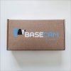
The controller is made in Latvia by company called BaseCam Electronics.
I had found it some time ago when was searching info about gimbals for APS-C Sony mirrorless cameras - The gimbal "Traveller Gimbal" : BaseCam Electronics
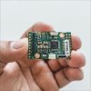
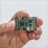
The controller is pricey a little bit, but small, light and 32-bit - SimpleBGC 32bit Tiny I2C 2-IMU Set, Revision B.
I got it already in next day after ordering.
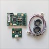
The controller comes with IMU, cable, ferrite rings:
Controller = 6 grams
IMU + cable = 2 grams
Ferrite ring (2psc) = 5 grams
The motors are 2x Rctimer GBM2804 100T each weighting 40 grams. If these will not be good, will exchange to iPower ones.
Weight so far 106 grams (controller, IMU, 2x ferrite rings, 2x motors, 4x dampening balls) without frame
About the frame. I wanted it to be built around cut carbon fiber like current gimbal I have made.
Had a talkd with friend from colleague times. He said he would help with 3D printed one (he is in company making commercial 3D printers, so it will be fun for him to help and see how it results).
Will be making sketch and visit him – his designer will help with final product in exchange of good beer
Will see how it finalizes in weight
Have in mind exchanging battery with dummy battery as controller can power the camera, maybe will gain some 15 grams, but will see.
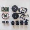
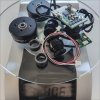
to be continued ...
As I mentioned in previous post, I already had motors from 1st build, but the 8-bit controller was waste time and effort, so I found another one.
The controller is made in Latvia by company called BaseCam Electronics.
I had found it some time ago when was searching info about gimbals for APS-C Sony mirrorless cameras - The gimbal "Traveller Gimbal" : BaseCam Electronics
The controller is pricey a little bit, but small, light and 32-bit - SimpleBGC 32bit Tiny I2C 2-IMU Set, Revision B.
I got it already in next day after ordering.
The controller comes with IMU, cable, ferrite rings:
Controller = 6 grams
IMU + cable = 2 grams
Ferrite ring (2psc) = 5 grams
The motors are 2x Rctimer GBM2804 100T each weighting 40 grams. If these will not be good, will exchange to iPower ones.
Weight so far 106 grams (controller, IMU, 2x ferrite rings, 2x motors, 4x dampening balls) without frame
About the frame. I wanted it to be built around cut carbon fiber like current gimbal I have made.
Had a talkd with friend from colleague times. He said he would help with 3D printed one (he is in company making commercial 3D printers, so it will be fun for him to help and see how it results).
Will be making sketch and visit him – his designer will help with final product in exchange of good beer
Will see how it finalizes in weight
Have in mind exchanging battery with dummy battery as controller can power the camera, maybe will gain some 15 grams, but will see.


to be continued ...
Last edited:
- Joined
- Aug 31, 2017
- Messages
- 80
- Reaction score
- 11
- Age
- 58
Outstanding stuff!!thanks Rob, you guys have been a big help.
I like the orange props too.
The cam remote is extremely useful with the Sony. It's powered off the unused gimbal cable.
The photo of the button keys shows the functionality. I shoot RAW and can easily flip from HDR brackets, to normal shooting, change ISO, Av, shutter speed, zoom in and out and shoot video- all without having to ground the Solo.
I am beginning to believe that a center anchored mount is unstable for these cameras. A bit why a catamaran is more stable than a single hull. If all the additional weight of these cameras is anchored only on the center line of the Solo, it becomes unstable and shakes.
I will be working on a new gimbal mount and will no doubt ask you for help.
Part.13-3 Brushless 2-axis gimbal (design, v1.0 print, sanding)
Project slowly moving forward (not much spare time in summer months).
With help of my friend from colleague’s time the approximate design was made, and parts printed (PLA, finall product will be from different, better filement).
This is only v1.0, but I wanted them to look like final product, so sanded them.
One part per evening – soft sanding with 120/240 and wet one with 1000.
The back-balancing plate turned out to be too long, so will reprint it shorter, re-sand it again etc. ?
Bottom plate tends to bent on point where camera is attached as it have no shoulder on other side, so will try to resolve it with adding a Velcro at camera side where motor is attached (Velcro camera to the side mount)
The top plate turned out nice, its beefier and holds the other parts and camera good.
The black screws are from nylon (to reduce overal weight) but holding the system perfectly.
This being told, v1.1 are already in progress and I will inform you here when it will be d0ne ?
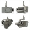


to be continued ...
Project slowly moving forward (not much spare time in summer months).
With help of my friend from colleague’s time the approximate design was made, and parts printed (PLA, finall product will be from different, better filement).
This is only v1.0, but I wanted them to look like final product, so sanded them.
One part per evening – soft sanding with 120/240 and wet one with 1000.
The back-balancing plate turned out to be too long, so will reprint it shorter, re-sand it again etc. ?
Bottom plate tends to bent on point where camera is attached as it have no shoulder on other side, so will try to resolve it with adding a Velcro at camera side where motor is attached (Velcro camera to the side mount)
The top plate turned out nice, its beefier and holds the other parts and camera good.
The black screws are from nylon (to reduce overal weight) but holding the system perfectly.
This being told, v1.1 are already in progress and I will inform you here when it will be d0ne ?


to be continued ...
Last edited:
As can be seen, i haven' t posted here for a while (almost 2 years), maybe was some how lazy + all that C-19 thing last years, but then @RichWest:

I have been sharing some info on 3DR Solo group in Facebook, but in those chat-type discussions valuable information disappears fast and is not transparent
as Latvians say: "neturi sveci zem pūra"
& to be continued ...
Yes I' m still flying my 3DR Solo, yes I'm still improving it, some upgrades are d0ne, and I will keep to update info hereYou guys keep on keeping on and share your accomplishments, don't be bashful . I really enjoy hearing and seeing the successes.
I'm just here hanging out until I can muster my time for Solo again. LLS...
I have been sharing some info on 3DR Solo group in Facebook, but in those chat-type discussions valuable information disappears fast and is not transparent
as Latvians say: "neturi sveci zem pūra"
& to be continued ...
Facebook or their groups just doesn't have the ability to archive a thought process linear. It's the way my brain works, maybe fine for the younger crowd...I prefer forums.
I'm not sure Google translate hits the mark..candle, under and dowry...I get the jest, did make me laugh.Latvians say: "neturi sveci zem pūra"
in english it would be something like : "don't hold candle under dowry"Facebook or their groups just doesn't have the ability to archive a thought process linear. It's the way my brain works, maybe fine for the younger crowd...I prefer forums.
I'm not sure Google translate hits the mark..candle, under and dowry...I get the jest, did make me laugh.
Part.13-4 Brushless 2-axis gimbal (build, rebuild, test, rebuild, test, ditch)
When I first time put together the gimbal from 3D printed parts, i found some flaws:
I actually got to working prototype on the table. If it behaves well on table , it doesn't mean it will do in the air.
1st - gimbal test on a table
2nd - gimbal test on a non flying drone
3rd - gimbal test on a flying drone
When in the air, by the sound could hear that drone is struggling, the gimbal was bouncing and resonating by itself
Thought, the problem is mounting point to the drone where default 3DR Solo gimbal sits
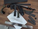
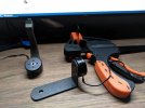
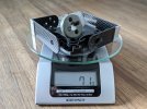
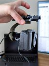
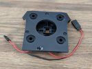
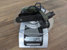
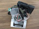
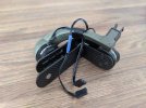
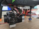
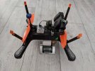
continue in next post
When I first time put together the gimbal from 3D printed parts, i found some flaws:
- one part needed to be printed longer as I could not balance the camera on horizontal axis, so it would be needed to reprint
- from the camera weight, parts seemed to bend and warp a little
I actually got to working prototype on the table. If it behaves well on table , it doesn't mean it will do in the air.
1st - gimbal test on a table
2nd - gimbal test on a non flying drone
3rd - gimbal test on a flying drone
When in the air, by the sound could hear that drone is struggling, the gimbal was bouncing and resonating by itself
Thought, the problem is mounting point to the drone where default 3DR Solo gimbal sits


continue in next post
Last edited:
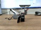
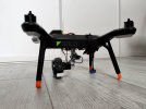
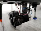
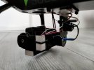
I rebuilded the gimbal frame, so this time it attaches where extension board attaches to 3DR Solo
But the problem persisted. I was bored with building and testing it, so I ditched the project to return to it later.
I think i found flaws, which can be improved:
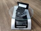
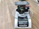
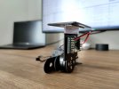
to be continued ...
But the problem persisted. I was bored with building and testing it, so I ditched the project to return to it later.
I think i found flaws, which can be improved:
- exchange L type arm which holds camera with U type, so anchor points are on both sides (due weight it tends to bend and warp),
- put motor on axis, instead of attaching it to the frame directly (due weight it tends to bend),
- more sturdier frame, so it can't bend, warp


to be continued ...
Last edited:
Part.14 GPS upgrade - from mRo to HERE 1 on mast
When I got my 3DR Solo, it was already equipped with mRo GPS chip from previous owner.
mRo actually is one of the best GPS available for Solo, HERE little better.
About HERE:
+ it has compass integrated (can get rid of Solo compass in leg),
+ it can be put on the mast (moving it further from other electrics and magnetic field created),
- it's not plug&play
- it's much harder to find these days
About Solo GPS:
REV A < REV B < mRo < HERE (so simple )
)
HERE GPS practically can't be found in continental Europe, so I managed to import it from USA. It is not plug&play, so I took connectors from Solo GPS and Compass (dropped schematic in pictures).
For GPS mast base used carbon fiber plate which attached to OEM Solo GPS mounting screws
First mast was Tarot TL8X005, but due vibration it tended to come upwards and get loose, almost fell of, so I later exchanged it with one from Holybro
I don't remember if i did something with configuration in MissionPlaner, did preflight calibration and restarted Solo I guess (please correct me if i'm wrong)
How it performs? Now I get satellites also in concrete building, more satellites and slightly better HDOP outside, no more toilet-bowl (previous leg compass got some negative impact from camera mounted on Solo belly. Mine internal compass is turned of by default)
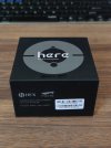
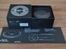
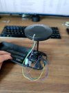
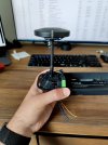
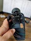
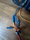
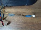
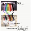
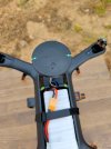

p.s. so I'm now having spare "mRo GPS u-Blox Neo-M8N / 3DR SOLO Upgrade" for sale on continental Europe
to be continued ...
When I got my 3DR Solo, it was already equipped with mRo GPS chip from previous owner.
mRo actually is one of the best GPS available for Solo, HERE little better.
About HERE:
+ it has compass integrated (can get rid of Solo compass in leg),
+ it can be put on the mast (moving it further from other electrics and magnetic field created),
- it's not plug&play
- it's much harder to find these days
About Solo GPS:
REV A < REV B < mRo < HERE (so simple
HERE GPS practically can't be found in continental Europe, so I managed to import it from USA. It is not plug&play, so I took connectors from Solo GPS and Compass (dropped schematic in pictures).
For GPS mast base used carbon fiber plate which attached to OEM Solo GPS mounting screws
First mast was Tarot TL8X005, but due vibration it tended to come upwards and get loose, almost fell of, so I later exchanged it with one from Holybro
I don't remember if i did something with configuration in MissionPlaner, did preflight calibration and restarted Solo I guess (please correct me if i'm wrong)
How it performs? Now I get satellites also in concrete building, more satellites and slightly better HDOP outside, no more toilet-bowl (previous leg compass got some negative impact from camera mounted on Solo belly. Mine internal compass is turned of by default)


p.s. so I'm now having spare "mRo GPS u-Blox Neo-M8N / 3DR SOLO Upgrade" for sale on continental Europe
to be continued ...
Last edited:
Similar threads
- Replies
- 4
- Views
- 2K
- Locked
- Replies
- 4
- Views
- 1K
- Replies
- 2
- Views
- 2K
