- Joined
- Sep 8, 2016
- Messages
- 302
- Reaction score
- 69
- Age
- 50


Atmega8Afrom what i can see in the opensolo github it seems to be a ATMega8
")
Soo... we're talking about a resistance-based voltage drop, and not a magnetics-induced rise in the local ground potential? Just wanna understand what we're talking about....Atmega8A
Most of the above is on average correct...
A few points...
It is "Ground Lift"
The Solo ESCs at full power can draw nearly 50A.... that is right... 50A. So 1V lift doesn't seam so bad now does it
The issue is an errata on the ATMega8A...
It sees a TTL high as >2.4V
However it should be >1.4v to be compliant.
So, at 3.3v from the PH2.0, a 1V ground lift is a very bad thing.....
Regarding changing the simonK firmware for Solo...
Simon K himself tuned that firmware to assist as much as possible in this matter...
I wouldn't be tempted to change so something else.
Remember, the exact parameters and calibration are all hard coded just for Solo...
A bit of both...Soo... we're talking about a resistance-based voltage drop, and not a magnetics-induced rise in the local ground potential? Just wanna understand what we're talking about....
.......
It sees a TTL high as >2.4V
However it should be >1.4v to be compliant.
......
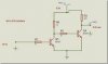
Not quite. Before 2.4 Ghz radios, all of the RC receivers seemed to use 5 volt signalling. Some of the Futaba FAAST receivers (and probably others) output 3.3 volt signalling, which did not work correctly with some servos. There exists three wire servo lead connected level convertor hardware to fix this problem.Nope. ESCs are designed to be connected to an autopilot or directly to an RC receiver. And RC receivers use 5 volt signalling. So any ESC should be fine with either level.
Not quite. Before 2.4 Ghz radios, all of the RC receivers seemed to use 5 volt signalling. Some of the Futaba FAAST receivers (and probably others) output 3.3 volt signalling, which did not work correctly with some servos. There exists three wire servo lead connected level convertor hardware to fix this problem.
Chris Shaker
Connecting a module that uses 3.3V signalling to one that uses 5V signalling is a recipe for disaster UNDER NON TYPICAL CONDITIONS.
.JPG")
This loosely translates to "If you want to find out all about crash-o-matic mode, send me a PM"If you are interested in a procedure that I have found to induce the ESC bug while in flight, send me a PM.
So the two possible fixes were...
An opto coupler on the ESC... (best option)
Increasing the voltage of the signal. (Green cube)

Well, I didn't wanna keep it all to myself. See, some other people wanna crash their precious Solos in the name of science, too.This loosely translates to "If you want to find out all about crash-o-matic mode, send me a PM"
")

@just_bruce please let me know how you achieved this. I wasn't able to break the ESCs so far with 3.5 and my parameter settings. Maybe I have overseen something ;-)If you are interested in a procedure that I have found to induce the ESC bug while in flight, send me a PM.
Sendeth me a PM.....@just_bruce please let me know how you achieved this. I wasn't able to break the ESCs so far with 3.5 and my parameter settings. Maybe I have overseen something ;-)
We use essential cookies to make this site work, and optional cookies to enhance your experience.