
Generic Battery + Arduino = Happy Solo
- Thread starter webbs
- Start date

You are using an out of date browser. It may not display this or other websites correctly.
You should upgrade or use an alternative browser.
You should upgrade or use an alternative browser.
- Joined
- May 9, 2017
- Messages
- 1,617
- Reaction score
- 660
- Age
- 46
Happy to forward some if you'd like. You set up and pay for shipping from me to you. These aren't on any ECLs that I know of.His response via eBay was
"Hi ship to USA and Canada only.
Been frauded 2 times by Aussies. Will not happen again, "
Looks like this won't happen unless i get myself a US shipping address.....
So webbs and I have been working on a few different PCB designs - there's more coming, but for anyone wanting a to use an Arduino Pro Mini and an external APM, we have come up with this (Though we realised may need ICSP header too, so needs updating to move the resistors to the back of the board to accommodate that, and shuffle some other things around to keep all the plugs accessible)
The idea is for it to be about this shape so it fits along side the battery, covered in heat shrink - much like spieky has done

The next iteration will have voltage sense and regulator on board, then another after that hopefully, that does away with the Arduino and uses just the ATMega chip and other bits required (should we include the neo's? maybe?)
The idea is for it to be about this shape so it fits along side the battery, covered in heat shrink - much like spieky has done
The next iteration will have voltage sense and regulator on board, then another after that hopefully, that does away with the Arduino and uses just the ATMega chip and other bits required (should we include the neo's? maybe?)
Last edited:
I ordered half a dozen of these from this guy.I looked at many different options for this but you would still need something to interface with the chip to the Solo as i couldn't find anything with SMBUS coms built in. This chip looks good in being able to carry out all the measurements and then could be integrated with and Arduino or similar.
Some of the chips that did have the SMBUS options then would have to stay with the battery as they report the capacity etc. based on counting current in and current out so this would be hard to move between batteries.
Great if you can get something like this working giving a more accurate cell reading along with current and temperature.
Thanks for the link, I have requested shipping costs for the plug to NZ so will see what that comes in at....
Payed, waited 60 days, then put in a claim which he bitched and moaned about.
But he did refund immediately.
There was never any record of dispatch, and of course none arrived.
I think this guy is scamming US.
Edit : it took 90 days for these connectors to arrive, and I had yo apologies to the seller and of course paid him back the refund he quickly gave me when I claimed.
So be aware, standard post shipping from Canada to Australia can = 90 days.
Maybe if contact the seller and explain you are aware of the 90 days shipping and won’t claim against him, he might be lenient and sell them.
Last edited:
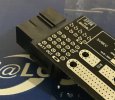
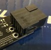
Almost done with the arduino version. Need to tidy things up and finish routing. I’ll post some 3d images once it’s complete. Happy for feedback or advice if I’ve stuffed something up. Cell numbers need updating, I have the wrong labels on the neo and am missing a capacitor on the INA169 for starters ")
Top (arduino, curr sense and all connectors. Battery traces are multi player, 5mm wide)

Bottom (Micro bec, fuse, voltage dividing resistors, shunt and exposed copper with vias on the -ve trace)

Top (arduino, curr sense and all connectors. Battery traces are multi player, 5mm wide)
Bottom (Micro bec, fuse, voltage dividing resistors, shunt and exposed copper with vias on the -ve trace)

The SMBOne is a nice board that can be configured for current (as the existing one does) or voltage, allowing you to enter your own voltage to percent matrix for the type battery you are using.
The powerful part is you don’t have to have a BMS with every battery, just install the BMSOne internally in the Solo and have a standard XT60 and Balance Lead connection and your good to go.

The powerful part is you don’t have to have a BMS with every battery, just install the BMSOne internally in the Solo and have a standard XT60 and Balance Lead connection and your good to go.
- Joined
- May 9, 2017
- Messages
- 149
- Reaction score
- 60
- Age
- 51
That is what this project is. It was started a couple of years ago as a BMS replacement so you can use any battery. It was designed as a DIY option and is open source. The code has a setup feature where you can calibrate for voltage and current. As it is open source you can modify the code if you want it to operate differently. The circuit boards above are an option. This setup can be mounted inside the solo and expose just an XT60 and balance plugs well. Being open source and DIY you can make it work how you like. There are people back in the thread who have soldered directly to an arduino and made a small cheap setup.
Yep, know about the BMSOne. As mentioned, this option is Intended to ‘drop in’ for those not wanting to heavily modify the solo. We’re going to include the solo plug footprint as well, which means no mods at all required to solo, and you can use stock batteries and normal LiPo’s interchangeably.The SMBOne is a nice board that can be configured for current (as the existing one does) or voltage, allowing you to enter your own voltage to percent matrix for the type battery you are using.
The powerful part is you don’t have to have a BMS with every battery, just install the BMSOne internally in the Solo and have a standard XT60 and Balance Lead connection and your good to go.
Don’t suppose you want to sell one of those connectors?
I have 2 or 3 now surplus to requirements, so yes.Don’t suppose you want to sell one of those connectors?
PM me.
I ordered some and it took 90 days to Australia.Looks like he has had issues shipping the plugs to Oz before so not shipping outside of the US or Canada.
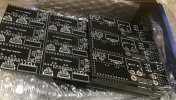
Prototype boards have arrived for the first 2 of 3 options. Please remember none of these are intended to replace the BMSOne, but rather provide a DIY/open source alternative. Will post some more photos and updates as build and testing progresses.
Option 1. “SoloSMBusLite”
Requires the least assembly (just the Arduino mounted ‘board-to-board’ and a handful of components) but it is dependent on an external APM power module to provide current sensing and the +5v for the Arduino. Mods to Solo also required to connect batt and I2C to mainboard.
Option 2. “SoloSMBus”
Designed to be ‘plug and play’ with no Solo mods required. Adds components for current sensing on board, along with options for XT and Solo connectors - no APM module required, but needs 5v mini BEC and Arduino mounted ’board-to-board’. I’d expect this to be the most popular for DIY.
Option 3. “SoloSMBus+” (still being designed)
Planned to be the same as 2 ‘plug and play‘ and includes all components onboard. This will be the most difficult DIY assembly, as there is a decent amount of components and SMT soldering/reflow required - no Arduino, APM module or BEC required.
Hopefully we’ve covered off the majority of use cases with the above options, but happy to consider others and take feedback or suggestions.
Attachments
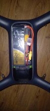
This is exactly what I am doing now. Not with BMSOne, but this one here.The SMBOne is a nice board that can be configured for current (as the existing one does) or voltage, allowing you to enter your own voltage to percent matrix for the type battery you are using.
The powerful part is you don’t have to have a BMS with every battery, just install the BMSOne internally in the Solo and have a standard XT60 and Balance Lead connection and your good to go.
View attachment 11490
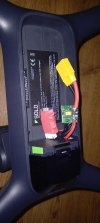
I bought two 6750 tattu batteries, and I am trying to hide everything in the front there. I still have to do the calibration, and then hide the stuff.
I will have a connector sticking out a bit more tho, but I plan to 3d print a tiny box to put it in
I removed the leds, jsut because I dont really need them on the copter.
I was also thinking about putting a velcro strap under the plastic... permanently.
BTW, is there any way to do the current draw calibration? or.. is it really needed?
Attachments
It is a very good idea to do the current calibration as there are variances in all current modules.
Search for current sensor calibration in the Arducopter Wiki for some methods that are very good and easy to do from some flights and log analysis.
Personally I hook a current measurement device and stick the sensor under load.
Search for current sensor calibration in the Arducopter Wiki for some methods that are very good and easy to do from some flights and log analysis.
Personally I hook a current measurement device and stick the sensor under load.
Thank you, I thought I had to somehow calibrate the arduino or something.It is a very good idea to do the current calibration as there are variances in all current modules.
Search for current sensor calibration in the Arducopter Wiki for some methods that are very good and easy to do from some flights and log analysis.
Personally I hook a current measurement device and stick the sensor under load.
So I can just shove the stuff back there, and do the calibration once everything is hidden. That is even better
- Joined
- May 9, 2017
- Messages
- 149
- Reaction score
- 60
- Age
- 51
In this setup you will need to calibrate it via the Arduino as it passes the info onto the Solo the same way the battery cells were calibrated. Ideally you would have a multimeter in series with the battery and try and draw around 10A, max for most multimeters. I'm not sure what the Solo will draw at 100% throttle with no props on.Thank you, I thought I had to somehow calibrate the arduino or something.
So I can just shove the stuff back there, and do the calibration once everything is hidden. That is even better
Similar threads
- Replies
- 1
- Views
- 2K
- Replies
- 6
- Views
- 4K
- Replies
- 1
- Views
- 2K
- Replies
- 8
- Views
- 3K
New Posts
-
 Free Music / SFX Resource for Your Videos - Over 2000 Tracks
- Latest: Eric Matyas
-
-
-
-