Bypassing Solo Motor Pods / ESC's

Joined
Apr 29, 2016
Messages
8
Reaction score
2
Age
61
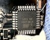
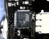
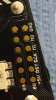
Hi Solo friends. I am transferring my solo electronics to a new folding frame I built and was wondering if anyone has figured out a way to bypass the motor pods/ESC's to use their own. My biggest concern is that there might be other electronics in the pod that have to talk to the main board. Loosing the LED lights does not bother me as I could easily install my own.
 
Any SimonK compatible ESC will work per the Solo GitHub site details. As well there are several posting here discussing an alternative ESC usage....

Hi Rich, thank you for your response. Unfortunately all the info on the GitHub site was a bit over my head. I'm gathering that most any simonK ESC will work. Now I just need to figure out what the 6 or so wires on the little white multi pin connector go to. Does anyone have info identifying the multi pin connector that connects the motor pod? So far I am only straight on the two small bullet connectors that supply power to the ESC.

GitHub - 3drobotics/solo-esc-simonk: Firmware for Solo ESC REV2 - Based on SimonK firmware
 
I saw a Solo tear down video from a user that called his company "Groom Lake Aviation" he was offering solo motor pod repairs. If any one has contact info for them, I would be willing to pay for someone to tell me what the one Red wire and the 7 Black wires go to ?
 
You will have to do some fact checking, but this is what it looks like to me:

If you start your counting from the red wire as pin 1...
Pin 1 - 88 Pin 11
Pin 2 - 88 Pin 10
Pin 3 - GND
Pin 4 - 8A Pin 32 (PWM Signal)
Pin 5 - Unknown or Not Used
Pin 6 - Unknown or Not Used
Pin 7 - 88 Pin 28
Pin 8 - 88 Pin 27​

I've attached pictures of the two atmel chips. The pin numbering on the atmel chips is clockwise, with pin 1 near the Circle/white dot.

It should also be noted that there are six copper pads on the PCB, each pad is connected to it's corresponding pin excluding pins 5 and 6.

@tngo, there are two chips on the ESC which can be flashed. To access them you need to hookup to the copper pads which are appropriately labeled for each chip. Check out the images.
 

Attachments

  • 170114_112758.jpg
    170114_112758.jpg
    1.3 MB · Views: 171
  • 170114_112822.jpg
    170114_112822.jpg
    1 MB · Views: 173
  • Screenshot_20170114-194207.png
    Screenshot_20170114-194207.png
    3.5 MB · Views: 186
Last edited:
  • Like
Reactions: Saijin_Naib
Thanks pious, I've noticed that also. Thx for the additional pics.

T
 
What are the stock escs capable of? I have found a motor I'd like to try but it will draw around 13a, will it be OK on the stock ESC?
 
Wondering if anymore info has been found on this. I am installing a different flight controller and now know which wires are for PWM input but would like to be able to have the leds lit. Not worried about different condition/colors, just would like them on. Anyone know what pins control the leds?
Thanks

Based on my experiment. The LEDs stay lid when power is applied and without connecting the 8 pin signal wires. I believe this will meet your requirements.

T
 
This should be useful.
Snimok.jpg
 
  • Like
Reactions: andrew.baker.142
what's the name/ P/N of the 8-pin connector used for motor pods ?
 
Does some one have a knowledge what i2c RGB LED driver will be compatible Solo Cube ?
 

New Posts

Members online

No members online now.

Forum statistics

Threads
13,094
Messages
147,748
Members
16,058
Latest member
Gabriela